
Diesel Service Report, September 4th, 2021
SF560 Fairbanks Morse H12-44 Restoration Project
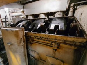
Previously, both exhaust manifolds had been removed due to leaking water jackets. They were repaired and are now reinstalled. There are two manifolds, one on each side of the engine block. There are six vertical cylinders in the engine, and when the lower piston moves down, it uncovers large openings on each side of the cylinder wall. Those openings leading into the exhaust manifolds. Each manifold, therefore, has six large square openings where the exhaust comes into it from the combustion in the cylinder. Each of the six openings, where exhaust gases come into the manifold, have eight ½” diameter studs to attach the manifold to the engine block. That means there are 96 total nuts to install and torque down to 70 ft/lbs and it is all deep inside the manifolds. Its very difficult to get to with a torque wrench.
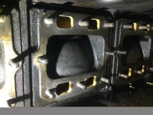 John Salvini and Richard Berk have now installed them and torqued down the nuts. The picture shows a large rectangular opening that the exhaust come out of. But it also shows four smaller openings where cooling water enters the manifold. During operation, engine cooling water helps keep the exhaust manifolds cooler. Its extremely critical that the gasket between the exhaust manifold and the engine block is in perfect condition and is seated tightly. That is the main reason why so many bolts are used and why they are so tight.
Now that the exhaust manifolds are installed, one of the next tasks will be to put water in the engine and inspect to make sure there are no further leaks. If that test turns out OK, then the rest of the reassembly can take place.
As discussed previously, the original mechanical driven cooling fan in the locomotive was replaced with an electrical fan at a scrap yard before we bought the locomotive. The problem that poses is that this model of Fairbanks Morse locomotive, had eliminated the generator that was used to power the older style electric fans. We have no sources for obtaining the correct fan at this time so will try to use the electric fan by powering it from the 64-volt auxiliary generator. Not only was the mechanically driven fan removed, but all the temperature switches and servo controllers for the radiator shutters were removed.
As a first attempt, we will use a thermostat to actuate a pneumatic valve for opening the shutters and a separate high current contactor for turning the fan on and off. We have tested the fan using 64 volts and it runs very well. But it leaves questions regarding how adequate it will be when the engine is heavily loaded during testing.
 Also, there is a thought that we should open the shutters long before the fan is turned on to limit the temperature shock to the radiators. During our initial testing, we have the option of manually opening the shutters. All these answers will be figured out once the engine is running and we have a chance to test it under load. At that time, we will do whatever in necessary to solve any issues that arise.
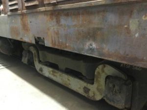
Tom Platten has started needle gunning old paint off the trucks. This picture shows one of the equalizing bars that he has started work on. The outside portions of the trucks will be cleaned this way, prior to sanding and painting.
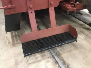
Carl Pickus has been working on reinstalling the front and rear foot-boards. The originals arrived at the museum with the locomotive but were then misplaced and not seen again for many years. Phil Palmieri rediscovered them a few months ago. When they were removed “from hiding”, they were all just mangled pieces of iron and sheet metal. Carl was able to save the main mounting bars and the rear foot shields but there was no way the foot tread material could be reused. Fortunately a company was located that had the exact size that we needed. This shows one of the new foot treads, with its associated rear foot guard, loosely sitting on two of the foot-board mounting bars. However, the foot guards need to be bolted to the new tread plates and the tread plates need to be bolted to the mounting bars.
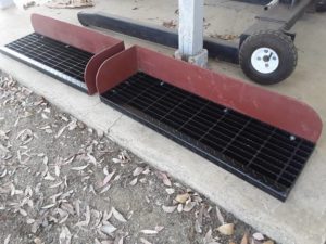 Carl began working on bolting the foot guards to the tread plates. This shows the first two that he finished. Once the foot guards are bolted to the tread plates, mounting tabs will be welded to the tread plates for bolting the assemblies to the mounting bars on the locomotive. When he is finished, they will look totally brand new.
Of course ffoot-boards are not legal anymore but we do install them for authenticity on some locomotives at the museum.
SP1006 EMC SW1 Switcher Locomotive
 When we were working on the engine during the restoration program, we noticed large dried chunks of dirt and oil sitting on top of the engine in a very inaccessible area under the exhaust manifold. The chunks almost looked like rocks. We cleaned out as many as we could reach but had to leave some in there. The engine is a V6 therefore there is an area between the two V banks of cylinders. After the restoration was finished and the engine was being used in service, we noticed loose oil in that area. We searched for the source of the oil but never were sure we found it. Our guess was that it was leaking from splashed oil off of the valve rocker arms or the cam shaft lobes. But that was just a guess. Eric Levin, our long time project technical supporter, was visiting a few weeks ago and we mentioned the problem to him. He suggested that we try to use oil splash shields that are used on newer model EMD locomotives. At least that would force oil splashed off of the valves and cam, to hit the shield and then drain back into the crankcase. Very little, if any oil, should splash onto the sides or cover of the valve compartment. Eric then sent us six of the shields to try. Frank Kunsaitis and Carl, analyzed how the shields should fit and concluded that a small amount of trimming of the shields would be required for them to sit down properly and not touch any fuel lines, throttle linkage, or cam components. Frank then modified all six of the new shield covers and installed them. He ran the engine for a few minutes and found that the shields worked perfectly. Hopefully the oil leaking will be stopped. If not, we will keep looking for the source. This picture shows three of the shields installed on one side of the engine. The other side of the engine has the other three shields. Thanks Eric.
– Dave Althaus