Diesel Service Report, August 28th, 2021
SF560 Fairbanks Morse H12-44 Restoration Project
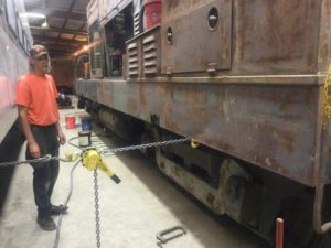
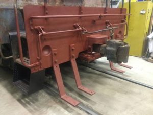 The metal work for the restoration project has been underway for a few weeks. Carl Pickus has fabricated or repaired all four of the lower access steps. He has installed the brackets for the front and rear foot-boards. New metal grates for the foot-boards should arrive this week. One of the new lower steps can be seen, painted black, in the lower left corner of the picture.
He also removed the homemade angle stops from both the front and rear couplers and cleaned up the wear plate areas under the rear coupler shank.
The front coupler measures 32.25” above the track while the rear coupler measures slightly over 32.75”. The desired distance is 33” plus or minus 1”. Since the front coupler is close to being out of tolerance and the old wear plate was very poorly welded in-place, Carl will remove it and replace it with a thicker plate to bring it up near the 33” specification.
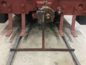 There is a special tool used for measuring the coupler height. It is a “T” bar with a small vertical ruler on it. The ruler is embossed with inch markings and the feet of the “T” bar rest on the track. This gives an accurate measurement from the top of the rails to the center line casting mark on the coupler.
The front coupler measured within specifications but since we are wanting everything to be close to original, it was decided to install a new thicker wear plate under the coupler shank.
Carl has also straightened a number of bends in the hand rails. They are now all correctly in-line and back to where they should be.
 Carl and Frank Kunsaitis then rigged a come-along to try and pull out a side skirt panel that had been pushed in slightly. It worked somewhat but the metal had been stretched and would not straighten completely. That area will most probably require body filler material prior to painting.
We knew that the brake cylinders most probably needed servicing and when air brake pressure was applied, two leaks were found. There was one on each of the two duplex cylinders. The only option was to disassemble them, clean them up and install new brake cylinder cups. Ryan Keck provided four of the cups which will be enough to refurbish the front truck. He has enough in stock to also do the rear truck.
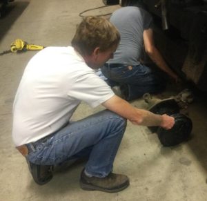 Tim Johnson, Bob Bray, Frank Kunsaitis, and with moral support from Tom Platten, the task of removing the brake pistons was started. This is one of the dirtiest jobs while maintaining Diesel locomotives. The pistons are covered with stinky old black grease. They are very difficult to access and everything must be cleaned and regreased before they are reassembled. The pistons were removed from the left side cylinder on front truck and were cleaned up. Then the cylinder must be wiped clean of old grease and have fresh grease applied. This work will continue next Saturday. It takes almost a full day to service just one of the duplex brake assemblies, and there are four to do. This shows Bob bray with one of the piston assemblies after it had been removed.
Earlier in the week, John Salvini and Richard Berk moved the locomotive outside so they had access to the Diesel engine sides with a forklift. They picked up the repaired exhaust manifolds with the forklift and placed them next to the engine so they could be pushed back into the cavity where they are normally mounted. This fitting process was needed to prove that the manifolds would fit correctly after the major rework that Carl and Jeff Williams had done when they rebuilt them a few months ago.
Both of the manifolds slid back into engine block correctly. This coming week, John and Richard will remove one manifold, check the mating surfaces, chase stud threads, and then apply the new exhaust manifold gaskets and manifold and torque the attaching hardware. When the manifolds are reinstalled, they will then pressurize the cooling water system to ensure there are no leaks in the repaired manifolds or the new gasket sealing surfaces.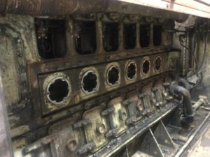
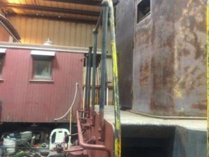
In the picture (left), the exhaust manifold is the large oblong assembly that has the six round holes. You can see how it fits tightly into an area in the block. When they tried to remove the manifolds a few months ago, the manifolds were stuck very tight in that cavity because standing water had not been drained from the manifold water jacket and when the water froze, it bulged out the bottom of the manifold. That essentially clamped the whole manifold in place. Fortunately, they were able to extract them with no further damage.
Nerd Alert
This next topic is a little long but may help folks understand an often-discussed topic regarding Diesel Engine fuel line lengths.
Traditionally on older style injection pump types of Diesel engines, it has been customary for Diesel engine designers and manufactures to install equal length fuel lines from the injection pump to the injection nozzle. There is no question that having the fuel injection lines the same length is the correct way to build an engine. If they weren’t the same length, then the question of injection timing errors must be considered. In the Injection Timing Blogs on internet, everyone has an opinion on this but none of them address the actual numbers associated with injection timing errors vs fuel line length.
Recently the question came up at the museum asking what the impact would be if a shorter length fuel line were used for one cylinder on a six cylinder engine. The shorter length would have been about 10% as a guess.
The reason this question is important, is that engine timing for firing of each cylinder is critical and engine designers are very careful to design camshafts, injection pumps and fuel distribution lines to eliminate as many timing errors as possible. It just makes sense to design errors out of the system. And so that’s how they have done it for the past 100 years or so.
But the question still remains, “What is the actual impact of having different length fuel injection lines?” To understand that question, the error amount needs to be expressed in degrees of crankshaft rotation. A typical number that many engines deal with is, as an example, 5 degrees before top dead center. Of course, that number is just a reference for this example. In the real world that degree number can be a lot higher depending on the engine.
Intuitively, a person might think that Diesel fuel is a non-compressible liquid contained in a steel none expanding fuel delivery tube. Then one might think that a pulse of fluid entering the totally filled fuel tube would result in an “instantaneous” pressure pulse at the other end. If that were the case, then keeping fuel lines the same length wouldn’t be necessary.
In reality, it takes time for a pulse of pressure to go from one end of the fuel line to the other. Of course, it’s very fast but it does take time.
After searching the internet, a study report was found that was called “Measurement of Biodiesel Speed of Sound and its Impact on Injection Timing”. It was written in 2003 for the National Renewable Energy Laboratory in Golden Colorado. Their interest was focused on the impact of using BioDiesel compared to regular Diesel fuel. As with all studies like this, calculations get very complicated. But the key that is needed to answer the fuel line length problem, has to do with the pressure pulse speed through Diesel fuel. And of course, it varies depending on temperature and pressure. So, with a pressure of around 3,000 PSI, and an average temperature, the pressure pulse will travel through Diesel fuel at about 4,600 feet per second. And that figure is shown in all kinds of charts in the study. It varies a little depending on the temperature and pressure but 4,600 feet per second is a reasonable number to work with. And just for interest, that is equal to 3,130 miles per hour. Its fast but not instantaneous.
The following calculations represent a typical locomotive Diesel engine.
- Assume the engine speed is 300 RPM
- Divide 60 seconds (= one minute) by 300 rpm = 200 milliseconds per revolution.
- Each revolution equals 360 degrees. So, if we divide 200 milliseconds by 360 degrees, we can see that each degree of revolution takes about 550 microseconds.
- Now we need to know how long it takes for a pulse of pressure to go through a fuel tube. The pulse speed is 4,600 feet per second which is 55,000 inches per second.
- If we have a fuel line that is 24 inches long, divide 24 inches by 55,000 inches per second and we get 436 microseconds for the fuel pulse to travel 24 inches.
- If we shorten the length by 10%, it will take 436 microseconds minus 43.6 microseconds which will be 392 microseconds.
- We know that one degree of rotation of the flywheel takes 550 microseconds and a 10% change in fuel tube length is 43.6 microseconds.
The conclusion I reach is that I know that at 300 RPM, 1 degree of rotation of the flywheel takes 550 microseconds. To change the timing of a single cylinder by just 1 degree, I would need to change the length of the tube enough to cause at least a 550-microsecond change. That appears not to be possible in the short fuel length runs that we work with. A change in fuel line length of about 10% appears to change the timing for a single cylinder about 1/10 of one degree.
With the tools that normal mechanics use for timing, a mechanic would be lucky to be able to set engine timing within one half of a degree of accuracy at the absolute best. No small amount of fuel line length variation can come anywhere near causing that much error.
My summary is that fuel line lengths should theoretically be the same length. It is well known that line length impacts fuel flow timing and it’s just good design practice to have them the same length. However, in a non-perfect world, in low RPM engines, a shortened, or lengthened fuel injection line of upwards of 10% of its initial length, will cause a fuel timing error of such insignificance that it won’t be detectable. In higher RPM engines, fuel line length errors could become noticeable in the 2000 to 3000 RPM range.
– Dave Althaus