Diesel Service Report, December 24th, 2020
I would like to take this opportunity to thank the volunteers that have worked so tirelessly this past year. With ten Diesel locomotives either fully operational or in-work, it takes a lot of effort to maintain them. Obviously, we don’t have the staff to deal with every detail but do attempt to keep them operational and address the major problems.
This is the group that has kept the fleet running:
Tim Johnson, Bob Bray, Taka Sakai, Tom Platten, Carl Pickus, Doug Newberry, Frank Kunsaitis, Richard Berk, and John Salvini. Thank you guys.
UP942
As you may recall, a traction motor lead connector failed two months ago. At that time, John and Richard repaired the connector but knew that the rest of the connectors needed to be inspected. The locomotive is now over the pit and the front truck has now been inspected. During the inspection, none of the connectors were found to have been overheating but two had broken ears and need to be replaced. These connectors are soldered on, so being able to do the work with the locomotive over the pit, makes the task much easier. The rear truck will be inspected next.
SF560 (Fairbanks Morse)
Earlier this year we found that all 12 fuel pump plungers were frozen in their down stroke position. We were able to exchange those for used operable ones. Now, one of those replace pumps has frozen. John and Richard identified the faulty pump and isolated it from the fuel rack. Then the Diesel engine was able to run again with just 11 of the 12 pumps working. Richard has sent the failed pump back to the supplier. They will disassemble it to see why it froze. Hopefully there isn’t something we are doing that is causing it. Water in the fuel is a prime suspect but we won’t know until they investigate it. We will know more in the next week or so.
As reported previously, the radiator cooling fan will be electrically operated because the original mechanical fan, and its drive shaft, were removed from the locomotive long ago. The electrical fan will be turned on and off with a modern locomotive thermostat that will replace and original non-functional thermostat. The original thermostat was so frozen in place that Carl had no choice other than to take it apart piece by piece and then use a hole saw to cut it out of the mounting pipe. Its removal will provide space for the new thermostat. Originally, the old thermostat controlled the opening of side shutters, top shutter, and the mechanical fan. The new design will control the temperature using just the electrical fan.
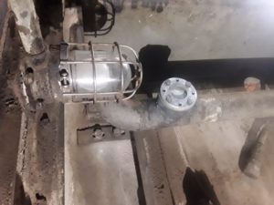
 This (left) is a picture of the old thermostat. Someone had attempted to operate the electrical fan using just the thermostat contacts. Of course the current for the fan was too high and melted one of the contact fingers. This is the thermostat had to be removed in pieces.
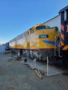
After Carl removed the old thermostat, he fabricated an 8 hole cover plate for the opening so that the locomotive can be used until the new thermostat is installed (right).
SCRM 1956
Frank replaced the two suction side fuel filters, and the engine ran fine after that. Operations reported that the new filters also solved a problem they were having when the engine throttle was placed back into the idle position. It seems that the extremely low fuel pressure was allowing the engine to stall.
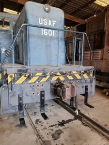 USAF 1601
Richard and John replaced a valve in one of the compressors that had been leaking. That solved the compressor problem that we have had with the locomotive for a long time. Now, the running gear is all back together and the air compressors work. The next step will be to change the engine oil and filters in both engines plus install new fuel filters. Then one of the cooling systems needs to be examined to see why it is losing water. Once that leak is determined, the cooling system will be refilled with water that has the correct corrosion additives.
Carl has been working on replacing the front and rear foot boards. He sand blasted and painted the original brackets and has all eight mounted. We have a high-resolution photo of what the foot-boards are supposed to look like so he has the information as to what material to make the foot-boards and side guards out of.
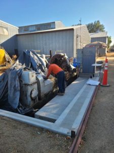
Sellers 50 Inch Wheel Lathe
Last week when I reported that the 480 VAC power cables had been pulled through the conduit from the Machine Shop to the lathe, I forget to mention that Todd Mowrey was also part of the crew. That was a very difficult task and it needed every person that was there to pull and push the cables. Thanks Todd.
The electrical power is connected to the lathe and the lathe is fully checked out from an electrical operation point of view. The tail stock on the right side of the machine moves freely both left and right. The main drive spindles turn smoothly and are variable in speed from 1.2 RPM to 8.6 RPM. That speed range should cover any cutting feed rate that we will encounter while re-profiling railroad wheels.
The major tasks now are to get a shed built over the lathe and to clean and refurbish the lathe from a mechanical point of view. The tool post cross feeds are very tight, as is the tool post itself. The main drive spindles are rusty and will need to be polished. The hydraulic clamps for holding the wheel set to the spindles have to be tested. Etc, etc. So far, great progress has been made but there is a lot more to do before the lathe is ready for wheel turning.
This (right) shows Carl getting ready to put the tarps back over the lathe after a very successful day of working on it.
Merry Christmas folks.
Dave Althaus
– Link to SF560 Fairbanks Morse H12-44 Restoration Project –