Diesel Service Report, December 18th, 2020
SELLERS 50” Wheel Lathe
Thirty-five years ago, a wheel lathe was acquired by OERM. It was located in Sacramento and shipped to the museum in a railroad gondola car. The lathe was unloaded from the gondola car and placed into a newly constructed pit. But it wasn’t that easy. Paul Dieges first had to measure exactly the location of the lathe foundation mounting bolt holes and then get the corresponding protruding foundation bolts correctly located in the concrete floor of a newly built pit for the lathe. When the crane lowered the lathe into the pit, the mounting bolts fit perfectly. Nice job Paul.
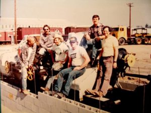 These (left) are some of the members that did the work. A few even had hair back then 35 years ago.
After the lathe was installed in the pit, the concrete foundation wasn’t worked on again until 2015. At that time Carl Pickus, Fred Nicas, and Doug Newberry, expanded it to incorporate a new design for the overall installation.
During the 30 years that the lathe sat idle at the museum, it was housed in a very rough tin shed that leaked water whenever it rained. The door to the shed was screwed shut and very few members knew that the lathe was even in there.
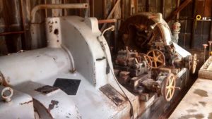 This picture (right) shows the lathe inside the shed shortly before the shed was torn down in 2015.
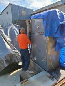
The lathe consists of the main lathe unit, shown in the picture, plus a control cabinet and a motor generator set that generates voltages for operating the system. The control cabinet was damaged in transit so Carl took it home to repair it. The power control circuits were totally missing so those had to be designed and fabricated from scratch. Carl then mounted the control cabinet to the new foundation. Of course, there was no roof over the pit or control cabinet, so tarps were used to try and protect things from the rain.
 The motor/generator assembly also went through a refurbishment. Carl mounted it on a steel platform that he constructed behind the control cabinet.
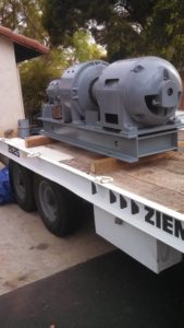
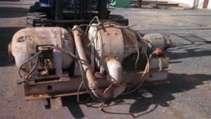
The first picture (right) shows what it looked like when we started the project. The next picture shows it as it is was after Carl refurbished it and was ready to bring it back to the museum. That end motor on the left in the first picture, is a 75 HP unit. The center piece is a generator that produces up to 250 volts to drive the lathe main power motor. The smaller unit on the right is the control voltage exciter that produces 250 VDC.
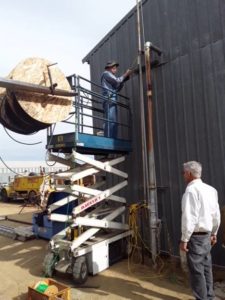
Then the project stalled for a few years due to other priorities associated with Diesel Locomotives. But a couple of weeks ago, Brian Smith inquired what it would take to get electrical power out to the lathe from the Machine Shop. We have had the wire for a few years so all it took was to get set up to do the pulling of the wire through conduits that had been installed about 5 years ago. Brian Smith, Phil Palmieri, Doug Newberry, Bryon Brainard, and Carl, pulled the wires so that electrical power could be connected to the lathe. This (below) shows Brian on the man-lift as they fed four cables into the conduit going over the circuit breaker in the machine shop.
 After the wires were in place, they were terminated in the lathe cabinet and then in the circuit breaker box in the machine shop. The next step was to test the 75 HP three phase motor. Power was applied to it and exceptionally large currents quickly blew fuses. After thinking about it, the best guess was that one of the internal windings inside the motor was wired backwards. The wires for the winding come out the side of the motor and the way they are connected determines which voltage the motor will operate on. But, it also assumes that the phasing of the three windings is correct. Unfortunately, the labels on the wires were all missing so apparently a few years ago, a guess was made as to which leads were phased the same. The three short wires were guessed to be the same phase. But we quickly found out that one was not correct. The two wires for one suspect winding were swapped and the motor then ran perfectly. This (right) shows Carl swapping the two wires.
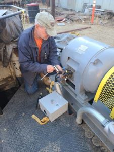
The next test was to see if the exciter generator would produce 250 VDC for the control circuits. It did not. The exciter commutator was cleaned with a burnishing stone and the field coil was temporarily connected to a 24 volt battery to reintroduce residual magnetism. Once that was done, the exciter generator produced the 250 volts, just like it was supposed to.
The next step was to test the lathe unit’s tailstock, which is the right-hand portion of the lathe. After some checking, two jumper cables were found to be missing. Originally, years ago, those terminals were wired with remote control heads but two of those are no longer with the lathe. Jumpers were installed and the tail-stock drive motor then worked. The tailstock was moved over its full distance. There are a few electrical details to still attend to in those circuits, but we know that the tail stock will move under its own power.
Then the final test was to see if the main drive motor would turn the spindles, which when in use, would turn the locomotive or car wheel sets being worked on. The START button was pushed and the spindles started to move immediately. They were tested for forward and reverse operation and it worked perfectly. The one issue remaining is to solve a spindle speed control problem. They only run at slow speed. We have all the documentation from 1946 when the lathe was built so it should be easy to track down the problem.
In summary, the lathe will work.
Now it needs to be cleaned and have all its parts lubricated and loosened up. The self-oiling systems also needs to be checked to make sure they are working.
Of course, with the upcoming winter rains, getting a new shed built over it will be a high priority. The other remaining work can also be accomplished after the shed is built.
And as is obvious above, this project has been almost a one man show. Carl Pickus has done almost all of the work with occasional help from others. Thanks Carl. We owe you for this one.
Dave Althaus
SF560 Fairbanks Morse H12-44 Restoration Project