Diesel Service Report, July 19, 2023
USAF 1601
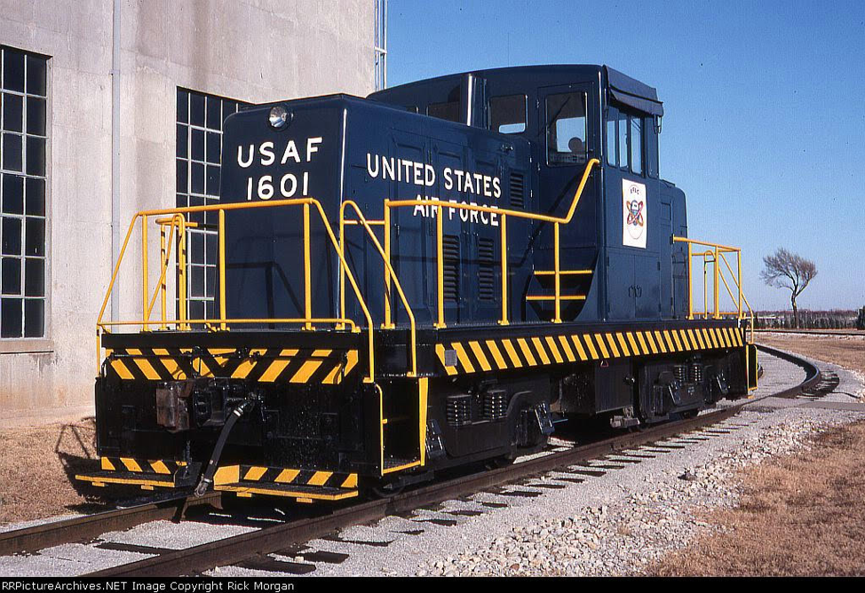 Starting last year, a slow water leak was noted on the number two engine. It kept getting worse until finally the radiator water had to be topped off every time the locomotive was needed. John and Richard used a high pressure sprayer to remove the calcified remains of evaporated water and coolant treatment chemicals. They isolated the leak to a faulty, maybe even missing, gasket. After a number of hours of removing parts to gain access, the water manifold on the Diesel engine was removed. The reason for the leak was then apparent. There was no gasket. Someone had previously tried to use silicone sealant instead of a gasket. John was able to find a replacement gasket and reassembled the cooling system. The leak was fixed and the engine is ready to use again.
A few weeks prior to that, the locomotive was used for many hours of switching duty. During that time, engine oil leaked our of the front of the #1 engine. That area was also then cleaned and the leak appeared to be a loose connection by the oil pump. That was tightened up and the leak seems to be fixed.
Another problem occurs that we haven’t tracked down yet. Sometimes when the engine start button is first pushed, the battery voltage goes to zero. Then when the button is pushed again, it acts normal and the engine starts. There are a number of possibilities but so far we haven’t spent the time to track it down.
UP942
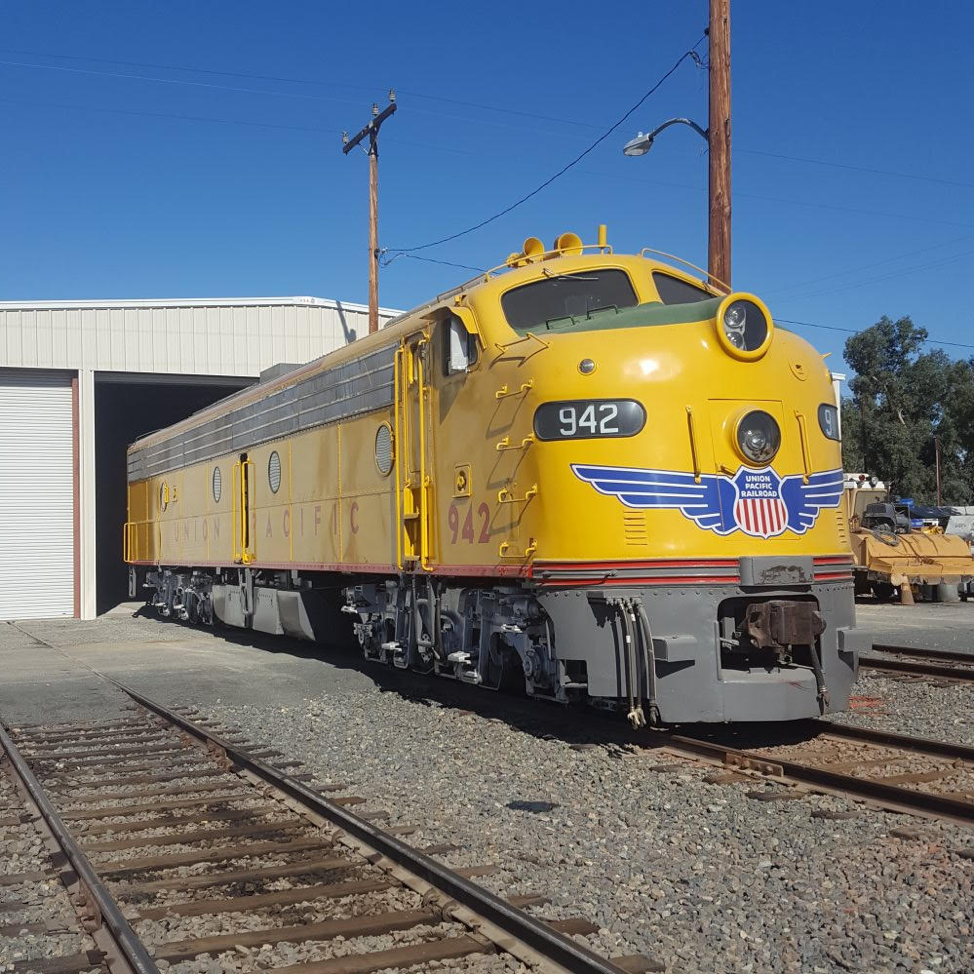 Engine oil was dripping down the side of the fuel tank. That has been common for many years but now it was getting really bad. John and Richard looked into it and found the engine oil drain pipe had been rubbing on a piece of steel and a hole had been worn through the pipe. Normally that wouldn’t be a problem but this time three things caused the leak. First, locomotive engine oil drain pipes are normally capped off using a pipe plug. That ensures that if someone accidentally opens the drain valve, lube oil won’t spill on the ground. It will be captured in that plugged pipe. And the plug was in place on this pipe.
Secondly, there is a globe valve that is supposed to be closed at all times unless the engine oil is to be drained. It was closed but not all the way. Since it was slowly leaking oil, that oil filled the plugged pipe and then escaped out the hole that was rubbed in the pipe. John then tightened the valve and used tie wraps to ensure the valve isn’t accidentally opened again.
USAF7441
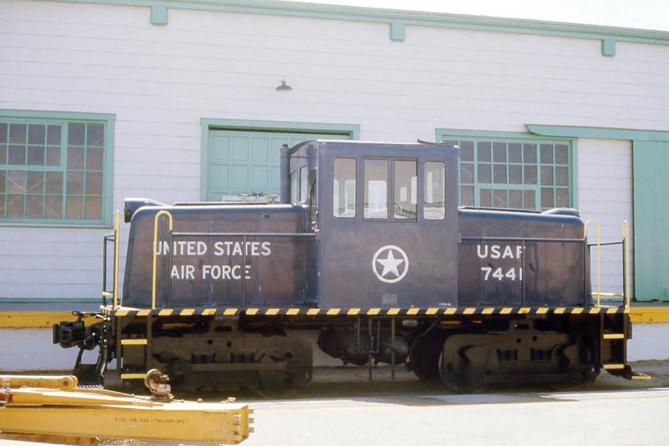 A new set of batteries was installed in the locomotive. These are golf cart batteries which are a lot cheaper than buying 8 volt locomotive batteries. The golf cart batteries are designed to be deep cycle types that work best with lower currents being used over longer periods of time. In this case two sets of batteries were installed in a series parallel combination to double the current capacity. We have done before but is still somewhat of an experiment.
After the batteries were installed, the voltage regulator for the number one engine was adjusted for regulating at 37 volts. That is the correct number for the locomotive. However, the generator on the #2 engine is not working. Most likely its a voltage regulator problem but we haven’t looked into it yet. The throttle system also seems to be sticky after not being used very often. If left idling, the engine RPM’s will slowly creep up. Most probably the problem will solve itself once the locomotive is used more often. And the other remaining problem is the loss of high pressure fuel prime in the #2 engine single disk fuel pump. After the locomotive sits for awhile, fuel apparently leaks back though a check ball that isn’t seating properly. The problem is that these fuel pumps are very difficult to work on. The #1 engine retains its fuel prime perfectly. That engine starts immediately as soon as the start button is pushed. The #2 engine requires hand pump pressurizing while turning the engine over with the start button. That approach works but it would be a lot easier if it worked properly.
SF560
 The restoration project continues. The good news is that we are planning to have a contractor paint the locomotive starting in early October. The plan is for the contractor to paint the locomotive black, then stripe it for the aluminum stripes, and apply stencils for the lettering, numbers, and Santa Fe decal. Then spray those areas with aluminum colored paint. There has been an on-going controversy for years regarding the stripes and lettering being painted white or aluminum. But even when Santa Fe ran the locomotives, both white and aluminum, and sometimes a mixture of both, were applied by the local Santa Fe shops. We will use all aluminum. Its our call and that’s what we’ve decided to do.
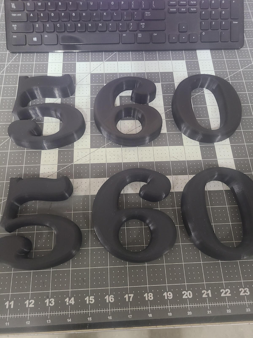
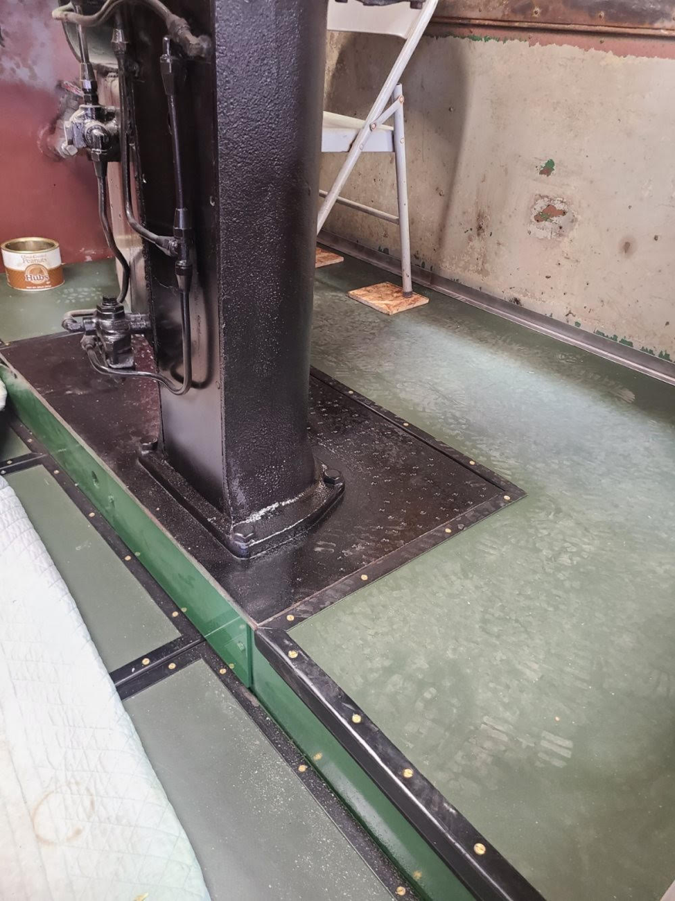 One issue that we needed to solve was how to find the correct 5″ tall raised numbers (560) to be applied to the nose and rear of the locomotive. Santa Fe had been using those raised style numbers on locomotives from the early 1900’s and even carried that through into some of their early Diesel locomotives. SF560 had those numbers but they were removed when Santa Fe repainted the locomotives to the blue and yellow paint scheme. That newer paint scheme directed that the front and rear numbers be painted on. So the old cast aluminum (or white metal) were removed. While researching this problem, a rail-fan contacted us and offered to 3D print the numbers at no cost. A copy of the number description and design was forwarded to him. He then built them out of hard plastic resin and shipped them to us. They arrived early this week. We will paint them aluminum and mount them in the same holes that the original numbers were mounted in.
The restoration work in the cab is still on-going. Corey and the guys are making great progress. The new floor is installed. Carl essentially replaced much of the plywood floor with new wood and then cut and installed new industrial linoleum over the top. Then he fabricated new metal trim pieces and installed those. The previous trim pieces were totally rusted away.
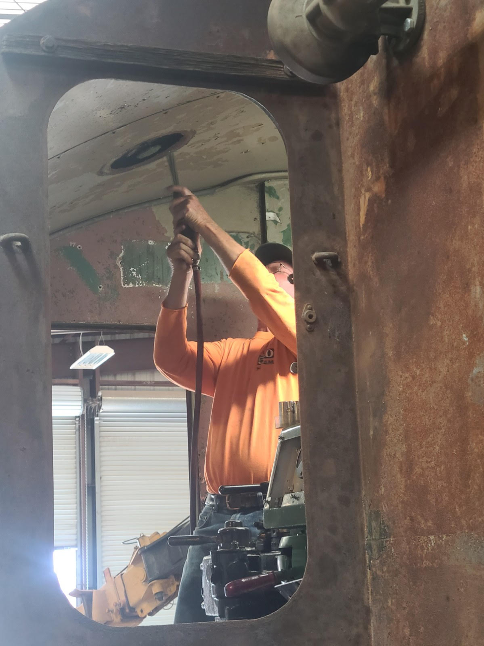
The next step is to prepare the walls and ceiling for painting. This (below) shows Carl needle gunning the area around the roof vent. Everything possible has been removed from the walls and ceiling to make it easier to paint. All of the gauges, plumbing, safety rails, sliding window rails, etc, have all been refurbished.
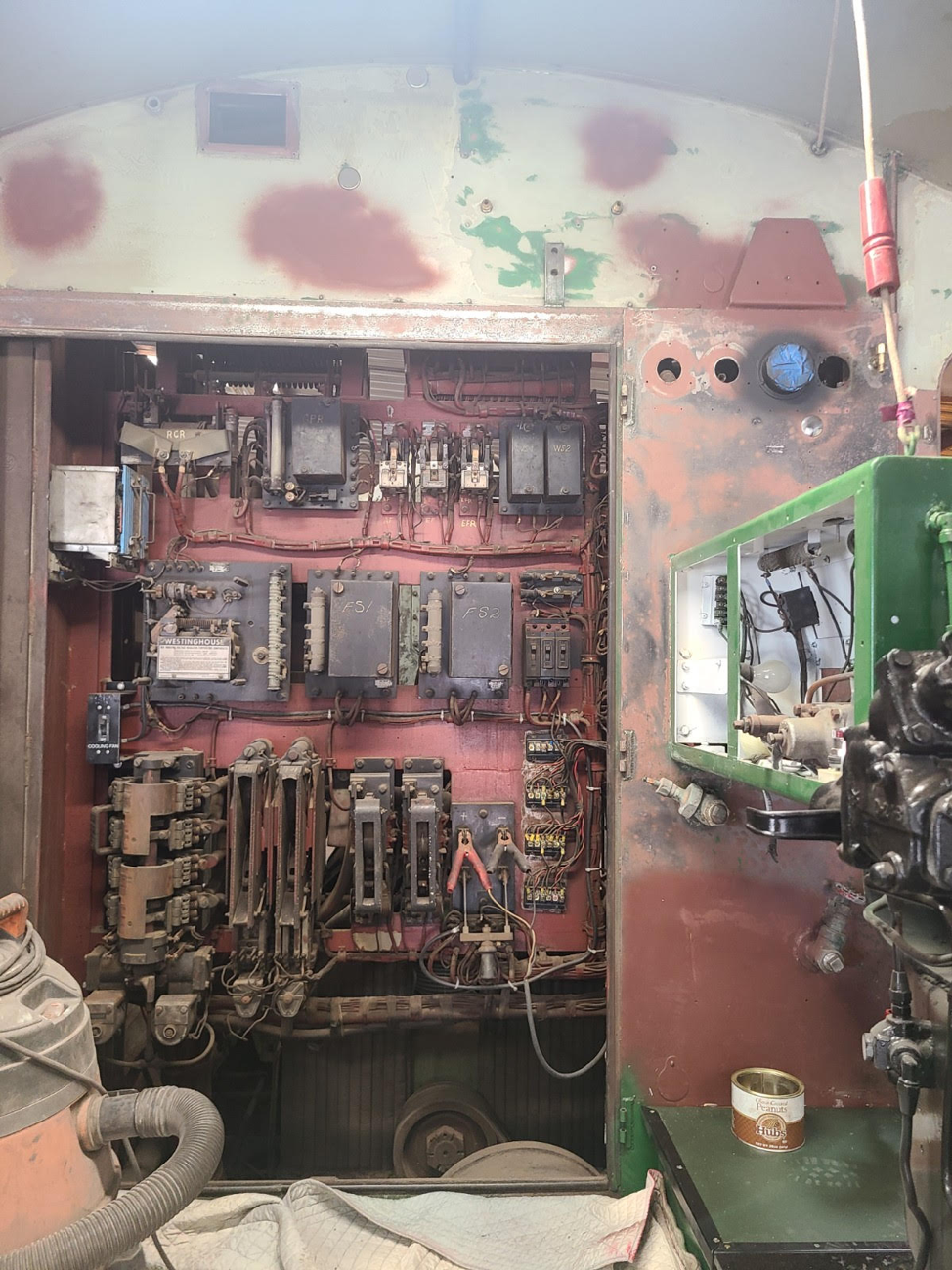
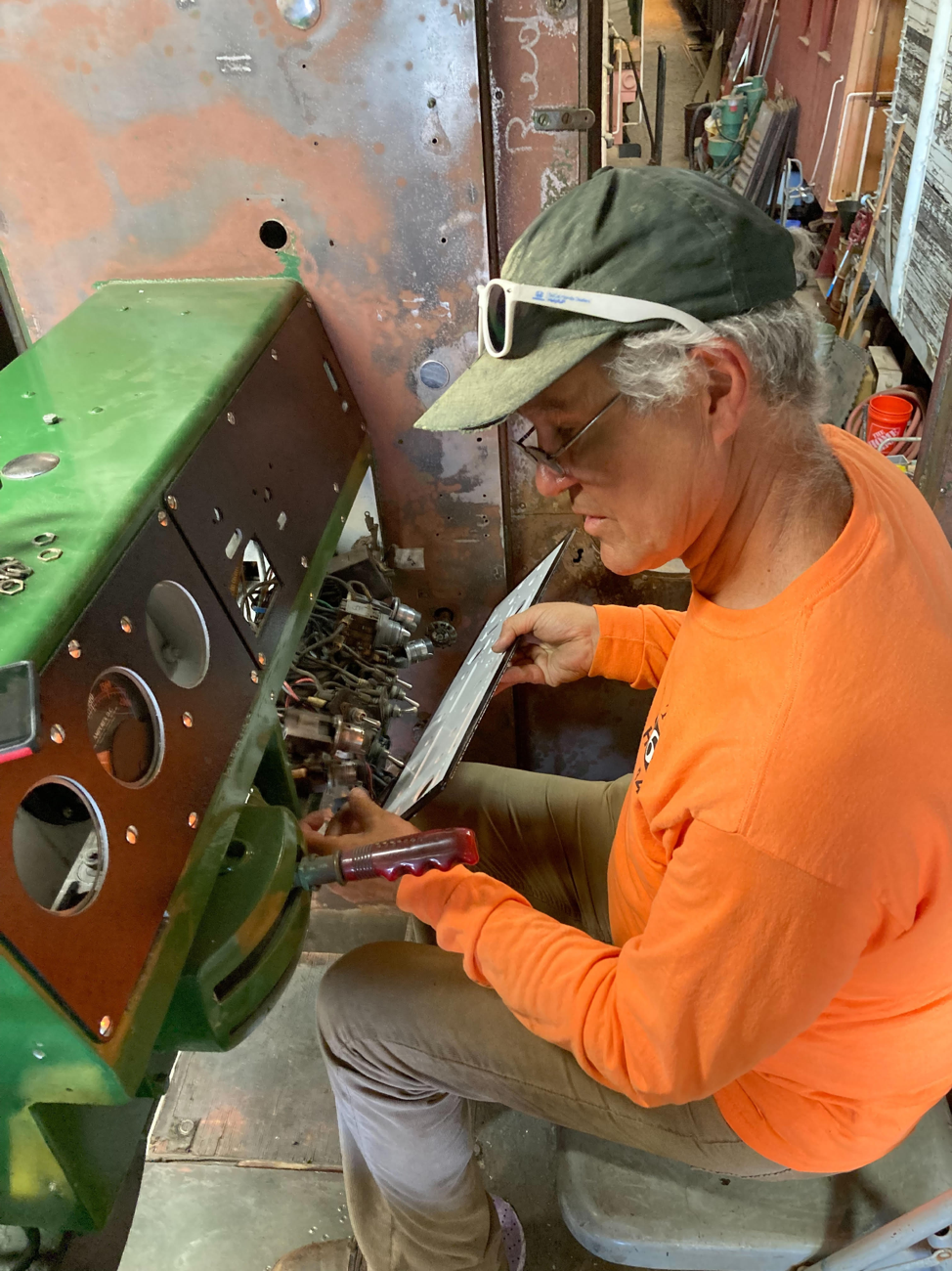
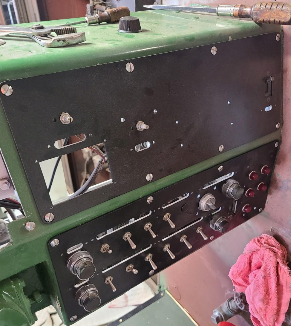
The engineer’s control console front panels were totally disassembled, the panels refurbished, the switches and lights cleaned and polished, and new identification plates are being engraved. This shows Corey as he is reinstalled all the switches on the lower panel.
Another on-going frustrating task has been to refurbish the cab sliding sash windows. It was assumed to be a straightforward job since many locomotive builders used the same window assemblies. The books showed exactly what size glass to use so four new pieces of glass were ordered. The aluminum frames were physically in good shape but were full of paint and corrosion. Those were taken to a company that sand blasted them and electroplated them for a new finish. The glass weather strip material was more difficult to find but a supplier was found. These older windows used 1/4″ thick annealed safety glass and newer locomotives used 1/2″ thick safety glass. Obviously the weather strip material is different for the newer 1/2″ thick glass. The correct material was ordered but took six weeks arrive. Once it was test fitted into the frames, it became obvious there was a problem. The new material is not the same dimension as was used back in the 1950’s. This newer material spaces the glass at .160″ away from the aluminum frame while the original material used .080″ spacing.
There is no way to modify the weather strip material. And as it is, the glass panels will not fit in the window. Glass suppliers were contacted about cutting down the glass that we already bought but none can do it without spending many hours of abrasive grinding. Cutting them down will cost more than buying new glass that is cut to the size to fit the new gasket material. And the exact old thickness gasket material is not available. We haven’t ordered new glass yet but it appears that we don’t have much of a choice. The amount of glass that needs to be removed is about .200″ from the top and one side. That isn’t enough material to cut with traditional glass cutting techniques yet is far more than can be easily removed abrasively. And water jet abrasive cutting doesn’t work because of the plastic sheet inside the laminated glass. That’s according to a glass supplier.
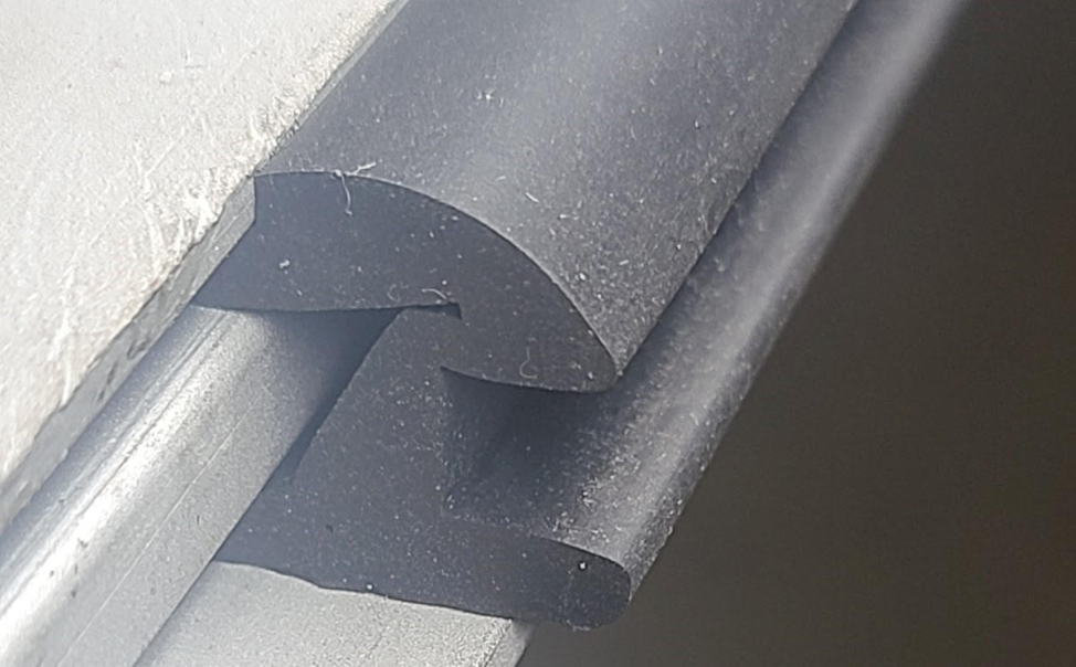 This (left) shows the window frame with a piece of the new weather strip material. Note how thick it is in the middle where the glass would sit.
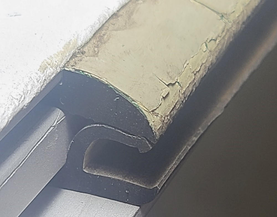
This next picture (below right) shows a piece of the old weather strip material in place. Notice how much thinner it is between the glass channel and the aluminum frame.
 That amount of clearance difference turns out to be a major issue. Further, the new weather strip material is very hard compared to pliable weather strip material that we use on many other windows. It is highly possible that this material sat on the shelf someplace for years, or it is freshly extruded material with a rubber shore hardness rating that is too high. There is no source for the guaranteed correct material so the problem will most likely result in having to buy new glass and actually cutting the aluminum window frame to get the glass installed. Its all possible but is a lot more effort than we ever imagined.
A special thanks goes to the very special group of folks that have been working on the project: Corey Wylde, Harry Pedersen, Tim Johnson, Bob Bray, Tom Platten, Frank Kunsaitis, Dough Newberry, John Salvini, Richard Berk, and of course the workaholic himself, Carl Pickus.
Thanks guys, job well done!