Volunteers for the week were Carl Pickus, Taka Sakai, Doug Newberry, Frank Kunsaitis, John Salvini, and Richard Berk.
SP3100
Last week the front truck was pulled sideways out from under the locomotive. It took a lot of planning and tool fabrication in order to make that happen. Below is the YouTube link of a time lapsed video of the extraction. Thanks to Andrew Temoshek for arranging for the video. It is interesting to watch.
Prior to the truck removal, the rear of the locomotive had to be braced and the front of the locomotive had to be jacked up and securely blocked. In addition, a come-along was used to apply the handbrakes on the rear truck while the locomotive is on jacks.
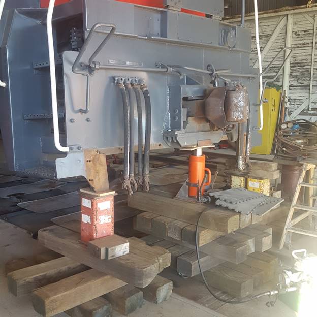
This picture shows three air jacks in place under the front of the locomotive. The two outside jacks, which are under the primary front jacking pads, were used for the initial jacking and the third one was added as an additional safety precaution during the final blocking procedure. Air jacks are screw jacks that offer safer jacking than hydraulic jacks. If a hydraulic jack were used, it could possibly fail if a seal or the hydraulic oil supply line leaked and the jack could collapse down. Screw jacks can’t fail like that. And we had previously obtained screw thread thickness gauges from Duff Norton to prove that the screw threads inside the jacks were not worn. Two screw jacks are safe and a third one just gives one more point for stability. On the back side of the furthest jack, you can see the slider rails and the slider carriage that were used to slide the truck out from under the locomotive. The tin shields over the sliding rails are in place to prevent dust and dirt from settling on the grease in the channels.
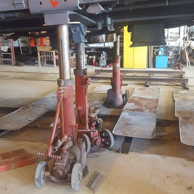
The front face plate of the locomotive was then blocked with solid steel blocking and wooden supports. The 100 ton hydraulic jack in the middle was used for final adjustments of tensions in the blocking. The hydraulic jack has pressure maintained in it but is not counted on for supporting the front of the locomotive.
Once the truck was removed, Carl, Richard, and John removed the #2 traction motor combo from under the truck and tipped it up on is tail to facilitate replacement of the wheel set. Obviously, it wasn’t as easy as it sounds.
However, before that took place, many man-hours were used cleaning the truck frame around the center bowl area. Once that was cleaned, everything in the area of the bowl appeared to be in good condition.
The first task, before removing the traction motor combo, was to chain the equalizing bars up to the truck frame so that when the journal boxes were removed, the equalizing bars stayed in place on the truck. Of course, the pedestal tie bars also had to be removed before the journal boxes could slide out of the truck frame pedestals.
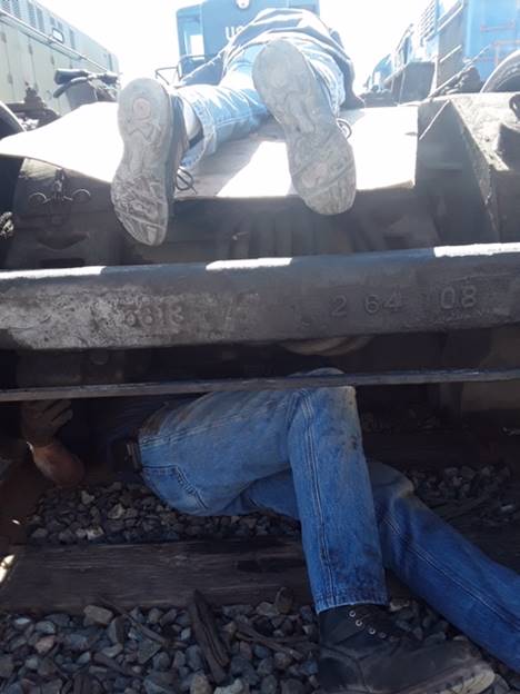
However, before the traction motor combo could be dropped from under the lifted truck body, the traction motor nose snubber pins had to be removed. These pins are so long that they can’t be dropped out the bottom unless the truck is over a maintenance pit or there is a hole in the ballast below the truck. As we continue to work with John Salvini, we are always amazed at what he does. In this case, he was able to crawl under the truck and lay on the ballast in order to compress the spring pack as part of the pin removal. This picture shows John’s legs sticking out from under the truck and Richard’s legs as he assists from the top.
After the traction motor nose snubber pins were removed, Carl used his large crane to lift the truck frame off of the #2 combo. The combo was then rolled back into CB7 where it was rotated onto its tail. In that position, the wheel set is suspended in the air which makes the replacement task much easier.
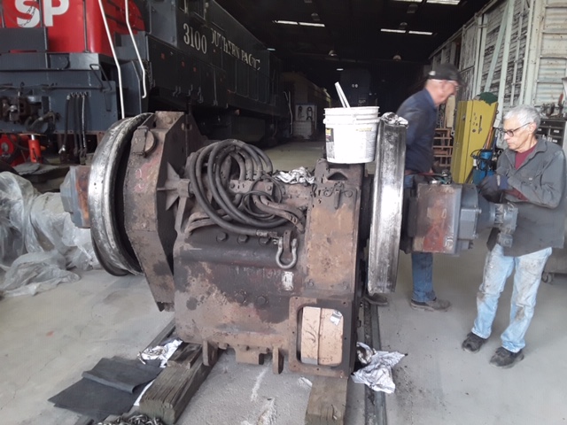
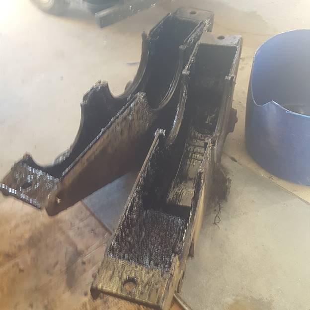
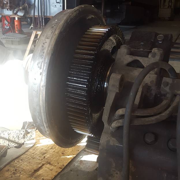
However, in the above picture, if you look just to the right of the left-hand wheel, you will notice a big steel case. That is called the gear case. It consists of two halves that clamp together around the traction motor pinion gear and the large bull gear which is on the axle. That gear case contains a very thick black grease. The next step was to remove that case. Carl torched off the Huck bolts that hold the two gear case halves together and slowly opened them to let the accumulated gear grease drain into a plastic tube. Once the grease was drained, the two gear case halves were removed and placed on the floor. A replacement seal kit for the gear case has been ordered. Gear cases are the ugliest nastiest greasy things ever invented!
This next picture shows the big bull gear that is covered by the gear case. The bottom of the large gear is submerged in the thick grease which provides continuous lubrication to both gears.
The next step in the procedure will be to clean up the areas around the traction motor support bearing caps that clamp the wheel set to the traction motor. Once the cleaning is complete, the bearing caps will be removed along with a sheet metal shield that extends between the two bearing caps. At that point the wheel set can be removed.
OERM 1956
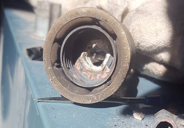
OERM 1956 was reported to have a non-functional front headlight. The bulb was removed for inspection and it was found that the center solder tip on the bulb base was burned away. A new bulb was installed, and it wouldn’t light either. As a first guess, additional solder was added to the bulb base center pin to ensure that good contact was made. That didn’t solve the problem. Close examination of the light socket revealed severe burning at the base where the center pin of the bulb should make contact. The socket was removed for overhaul. Taka was able to locate an exact replacement socket and should have it all repaired by next Saturday. This picture shows the interior of the socket that burned away. The bulb is rated at 34 volt 250 watts. That is a tremendous amount of heat and burned up sockets is an ongoing problem in locomotives that used these types of bulbs.
Coolant Flushing
Several months ago we began a process of flushing out locomotive cooling systems and refilling them using fresh water that was mixed with a corrosion inhibitor. In the old days, corrosion inhibitors were chromate-based chemicals which are heavy metal toxins in the environment. We don’t use those toxic additives and haven’t used them at the museum. Our locomotives were operated with only fresh water for many years.
The problem of course was that there was no rust or corrosion control for all those years. As a result, the cooling systems in our locomotives became very corroded and plugged up. Early last year we flushed all the cooling systems and added new, environmentally friendly, corrosion inhibitors. But as time went on, we saw those inhibitors slowly disappear as they reacted with the corroded systems. In a short time, there was no evidence of the inhibitors left in the cooling system.
We then attempted to buy inhibitor chemical in bulk, but that supplier was unable to supply it. We then switched to a different supplier and purchased a pallet load of liquid inhibitor concentrate in gallon jugs. We know that the inhibitor formulations are different between the two suppliers and didn’t want to mix them. The decision was to again drain the locomotive cooling systems and refill them with the new chemical.
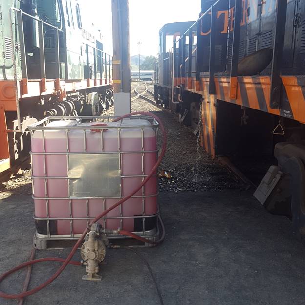
Jeff Williams provided two 264 gallon plastic totes for us to do the premixing in. We added just over 4 gallons of concentrate to a single tote while it was filling with water. The result is that we have a fresh coolant mixture that is purple in color like “Hawaiian Punch”.
That then gets pumped into the locomotive cooling systems. So far, we have flushed and refilled OERM 1956, SP1474, and USAF 7441. We will continue to flush and refill the rest of the fleet as time allows. Below is a picture of a full tote of fresh coolant. In front of the tote is the air operated pump that we use to transfer the treated coolant into the locomotives.