Diesel Service Report, October 20th, 2021
ATSF 5704 EMD SD45-2 Restoration
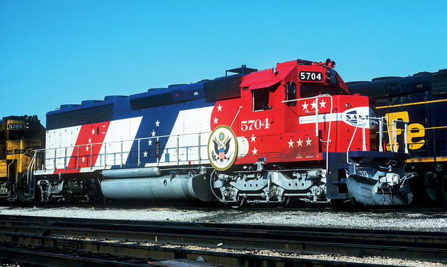
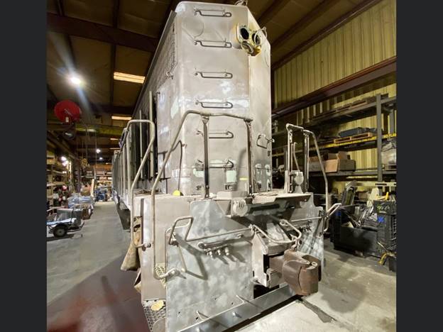
The cosmetic restoration of Santa Fe SF5704 Bicentennial EMD SD45-2, continues in Kansas City. There is no identified schedule for the delivery of the locomotive to SCRM, but hopefully it will be in the next few months.
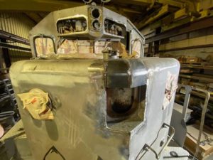
Once the delivery schedule is announced, rest assured that the Railfan community will document its every move during the trip. The locomotive has been grit blasted to remove all the old paint and extensive metal work is under way to restore the locomotive back to its 1976 configuration. Stephen Priest, the project originator and coordinator, posted these next two pictures on the SCRM Diesel Service Facebook page. They show the extent of the work that is underway.
After the locomotive arrives at SCRM, work will commence to restore it back to operational status.
SF560 Restoration
 Tom Platten has finished needle gunning the trucks and side rails of the locomotive. His next task will be to use a rotating wire wheel to remove additional loose paint and smooth the edges of the paint that wasn’t removed.
Tim Johnson and Bob Bray are continuing to work to replace all eight brake cylinder piston boots. They have the first one done and are working on the second one. Access to the pistons is very limited and they had to lower the brake rigging onto the ground for access to the second piston. It is becoming clear that replacing the rear truck brake cylinder boots may require jacking the locomotive off the truck to gain clearance. That will be a lot of extra work, but we may not have a choice.
We have thought about removing the trucks for inspection and cleaning, as part of the restoration, but had not made that decision yet. Once the Diesel engine is proven to be functional, we will decide if we need to remove the trucks from under the locomotive. There is lot to be gained by doing it, but we know it’s a big task that we hadn’t planned on.
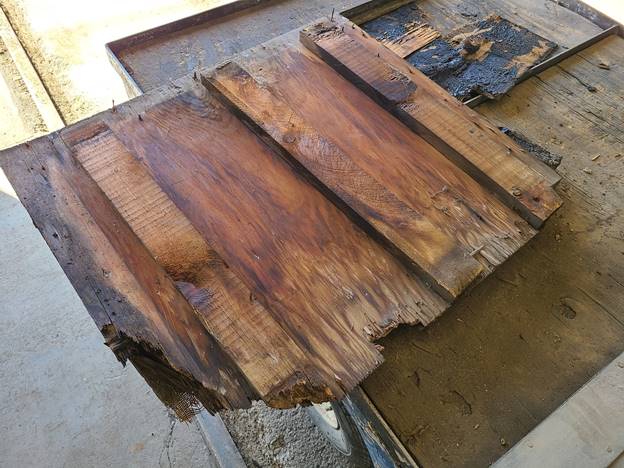 Carl Pickus has removed a portion of the cab exterior back wall. There was major damage from rust and new sheet metal will be installed. When he removed the rusted metal, it exposed severely rotted flooring wood. Carl removed a couple of those pieces and will be making new replacements. One question that isn’t answered yet has to do with the floor covering. It looks like very thick industrial linoleum with a burlap backing.
The rear headlight lens was purposely broken out by kids throwing ballast rocks shortly after the locomotive arrived at the museum. Frank Kunsaitis removed a replacement lens from one of the Trona Baldwin locomotives that are used for spare parts. The headlight assembly on SF560 was made from aluminum and the lens door hinge pin was made from brass. Over the years, corrosion has welded those two metals together. There is no obvious option to repairing this problem other than to remove the complete assembly and drill out the brass hinge pin. The headlight assembly will then go through a complete rebuild while it is off the locomotive.
John Salvini and Richard Berk have finished installed the water jumper tubes that fit between the water cooled exhaust manifold and the engine cylinder outside walls. There are 12 of these water jumpers in the engine. When Richard and John were ready to install them, they noticed that they didn’t have the correct seals. And a check with our supplier turned up just one of the correct seals and there was no cost effective option for obtaining more. A review of the sealing area showed that a modern O-Ring would most probably work.
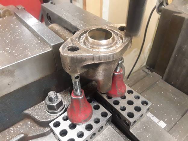 The first 8 were installed with O-Rings. The remaining four jumpers were a different design and needed to be machined for proper mating to the O-rings. Carl Pickus took the four home and milled them down. John and Richard then installed those four and they fit fine. This shows Carl’s vertical mill set up for the machining.
After the jumpers were installed, Richard and John filled the locomotive cooling system with water. There were no leaks detected in the rebuilt exhaust manifolds or the water jumpers. The only leaks noted were two small dribbles coming from around fuel injector adapters on the side of the cylinder walls.
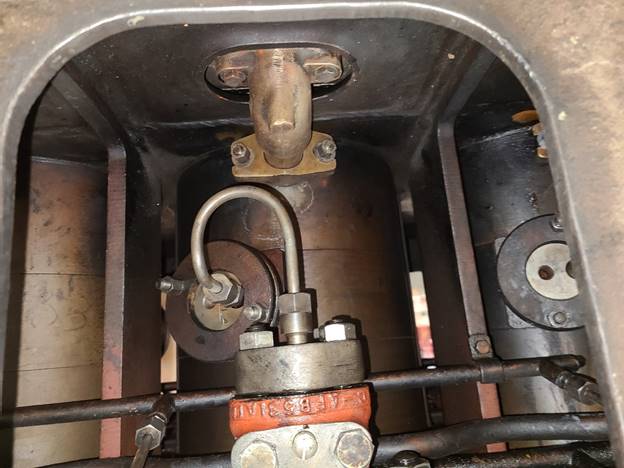 This shows the brass jumper in the middle of the picture at the bottom. The injection pump is above it with the orange housing. The bent tube goes to one of the injectors in the cylinder wall. That is the area where two small leaks were observed. Hopefully the leaks can be stopped by tightening the injector clamps.
The next step will be for John and Richard to isolate the Diesel engine cooling system from the rest of the locomotive. Then fill the engine cooling system with water and pressurize it up to about 23 psi. That seems like a very high cooling system pressure but that is what Fairbanks Morse says the system can experience for head pressure out of the centrifugal pump at certain RPM’s.
Below is the data chart that FM provides. Notice how the pump almost loses head pressure up at the maximum horsepower setting. But also notice that the gallons per minute is still increasing. The water flow is what provides the cooling but its obvious that the pump is reaching its maximum ability to pump adequate water at those RPM settings.
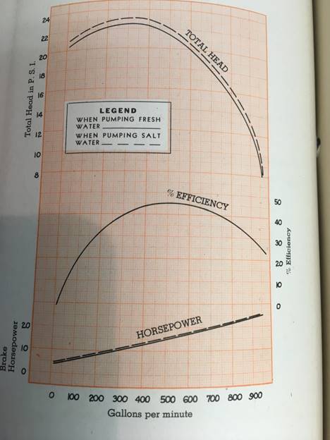
After the high pressure testing of the engine cooling system, the rest of the engine will be reassembled for operation.
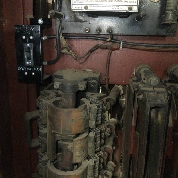
As mentioned previously, the locomotive does not have its original mechanically driven cooling fan. Someone removed that fan and installed an older style FM electric fan. But this short length model of locomotive didn’t have room for the correct fan generator so there is no way to power the fan as it was designed to be.
Our only option is to try and operate the fan from the 75 volt DC battery system. That system has a 7.5kW generator supplying power. Divide the two figures and you see that the generator can provide 100 amps of current. The required electrical components have been installed to open the radiator shutters and turn on the fan using the 75 volt system when cooling water reaches 170 deg F. When the fan is running, it takes 50 amps of current. That leaves 50 amps for charging the batteries and operating other things such as headlights, coils, contactors, engine room lights, etc. We had no other option so will have to wait and test the system to see how much power we really have available to run the fan. The 75 volt generator is rated at 100 amps at full RPM. We don’t know what it will do at idle. It may not generate enough current. But we also know that FM engines habitually run cold unless they are under heavy loads. The cooling fan may never come on in our normal operations.
 At the museum, we never operate under heavy loads or at high RPM’s. Most probably the engine will never reach the 170 degrees to trigger the shutter and fan thermostat. The only time we are most likely going to run into issues is when we connect the locomotive up to the resistor load box and force the engine to operate at high power levels for burning out the exhaust system. Then we will be able to see if the fan has adequate cooling or if we need to reduce the testing power limits. All of this will be worked out as the restoration progresses. But at the bottom line, we think it will all be OK because of the low power levels we operate at in normal use.
As a final option, we will have the ability to open the radiator shutters and not turn on the fan. Air will flow though the radiators and provide some cooling and we will save 50 amps of current, if that free-flowing convection air has a significant impact. The picture below shows the added switch in the electrical compartment that can turn off the fan if needed.
– Dave Althaus