Diesel Service Report, November 18th, 2021
The SF5704 Bicentennial EMD SD45-2
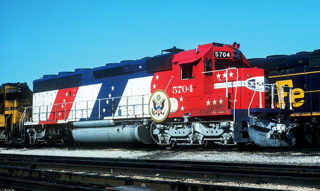 Stephen Priest, the project Founder and Coordinator, reported that most of the restoration metal work has been completed. The locomotive will be going into the paint shop at Mid America Car Co. in Kansas City sometime soon. The locomotive will look like this (left) when it arrives at the museum sometime in the next few months.
However, Mid America is going through a tremendous amount of work to make it look like the 1976 picture above. They grit blasted the complete locomotive and are restoring it back to the exact 1976 configuration. 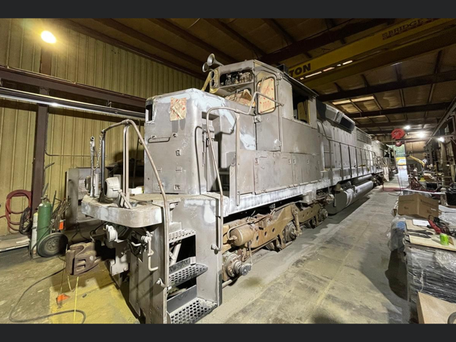 That meant relocating the headlights, removing ditch lights, installing a pilot plow, and reworking many items on the roof and making dozens of other repairs. The photo below shows the locomotive in the shop at Mid America. That picture demonstrates the level of detail that Mid-America Car, Inc. is noted for. No details were overlooked. And of course, Stephen Priest is a renowned expert on Santa Fe locomotives and is the author of “Santa Fe Railway Diesel Locomotive Painting & Lettering Guide for Model Railroaders”. And no one is more attuned to minute detail than hard core Model Railroaders. And Stephen is the ringleader of that group for Santa Fe locomotives.
SF560 Restoration
In Summary, the Fairbanks Morse Opposed Piston Diesel engine is all back together. It has been started and operated a number of times now. When it was moved, under its own power, back and forth from Carbarn 7 to Carbarn 4, five or six times, it ran smooth, the brakes worked well, and no oil was spitting out the stack.
Prior to the operation,Tim Johnson and Bob Bray had started to change all eight brake cylinder cups. It is a very difficult task if the trucks are under the locomotive and it was obvious that the rear brake cylinders were going to be almost impossible to work on. As such, they finished the brake cylinder repair on the Fireman’s side of the front truck and then reassembled everything. Ryan Keck fabricated new brake hoses for the connection between the locomotive body and the trucks. The new hoses were installed and the brakes tested.
Tom Platten has continued working on cleaning the trucks but access is very limited. The decision has been made to remove the trucks for further cleaning, painting, inspection, and replacement of the remaining brake cylinder cups. but the truck removal won’t be done until after the Diesel engine work is compete.
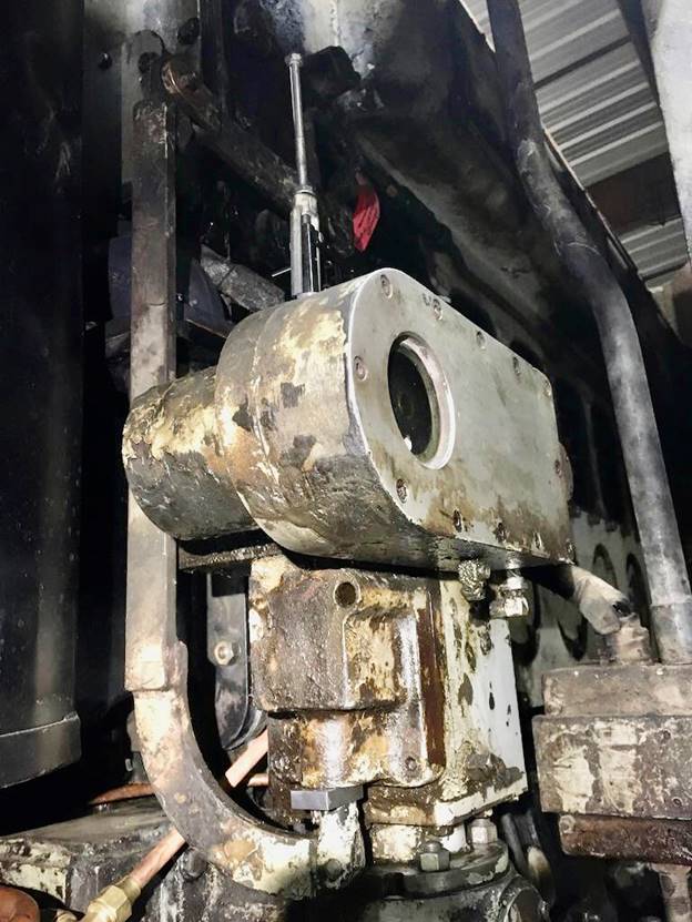
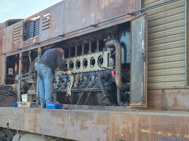 In the picture (left), the brighter horizontal plate with the large holes in it, is the engine stiffening plate. There is one each side of the engine. It tightly clamps the upper half of the engine block to the lower half. It’s a critical piece of the engine design. Richard Berk and Scotty, out visitor from back east. installed both stiffener plates. During assembly, one stud on an exhaust manifold inspection cover had stripped threads. Left, Scotty is replacing the stud.
After the exhaust inspection ports were closed, Scotty replaced a fuel line that was severely damaged. He also removed the derail clips that are meant to keep tucks attached to a locomotive in case of a derail or roll over incident. Those needed to be removed before we can jack the locomotive body off of the trucks when the time comes.
Richard Berk and John Salvini finished installing the cooling water plumbing but needed a Marman coupling that we didn’t have in stock. They had a used one, but it would not seal correctly. A replacement coupling is being shipped to us.
John reinstalled the governor and connected the throttle linkage to the fuel racks. Once the engine was started, the fuel system seemed to be operating close to normal. However, Richard felt that it was worth the effort to recheck the governor settings, but we didn’t have the correct tools. One tool was a 3/8” spacer block that is inserted around the governor piston power shaft. Carl Pickus quickly fabricated that. Then a “jacking tool” was needed to pull the governor piston up to a certain position. We didn’t have one of those tools either. Fairbanks Morse engines are notorious for needing lots of special tools. In this case, Richard fabricated one out of a standard turnbuckle, making it look like the tool in the Fairbanks Morse book. That tool, along with Carl’s spacer, allowed Richard to make the measurements on the fuel system.
 Everything seemed to be correct. This picture shows the governor with the jacking tool on top and Carl’s spacer being used below to hold the governor power piston in a certain position. And yes, the whole engine is that dirty, or worse.
This coming Monday, the engine will again be started. Assuming no further problems are found, Richard and John will attach it to the load box. They will then test the engine up to about 450 horsepower or so. Hopefully that will get it hot enough to burn out loose oil in the exhaust system. At this point we don’t know how fast the engine will heat up, or if it will even get hot enough to clean out the exhaust system, or if the cooling system is severely compromised due to clogged radiator cores. Those are things that the load testing should reveal.
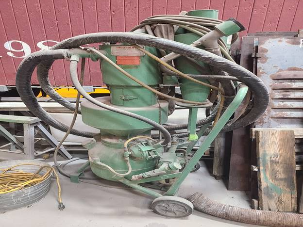 The outside metal of the locomotive is severely rusted. It would be a tremendous amount of hand sanding to get the rust removed adequately for painting. On the SF108 project, Jeff Williams used a grit blaster that recycled the abrasive grit. He used very small steel shot for grit media. We are investigating that blaster and hopefully will find it adequate for removing rust from SF560. There is no operating manual for the Vacublaster but we think we can figure it out.
Fairbanks Morse Souping Problems
In the Diesel Locomotive world, “souping” is the term commonly used to describe when locomotives blow liquid oil droplets out the stack. This oil is very black and makes a mess of everything around it, especially downwind. Usually, souping is associated with 2 cycle Diesel engines, like EMD’s and Fairbanks Morse.
The Fairbanks Morse Engines are notorious for souping. Most pictures seen of well used FM locomotives show black streaks all around the exhaust stacks. Our locomotive had been souping for so long that the oil, mixed with West Texas Dust, formed a hard thick asphalt on the locomotive walkways. As part of the restoration, we need to understand what was causing the souping and see if we can devise a way to stop, or at least control it.
The first effort was to inspect the exhaust manifolds to see if there was loose oil in them. John opened the exhaust manifold inspection covers and found gallons of loose oil in there. Then he inspected the input to the snubbers and found they were almost totally plugged with thick carbon chunks and more loose oil. It quickly became obvious that we had to remove the exhaust manifolds for cleaning and repair and snubbers for cleaning.
It also became obvious that Fairbanks Morse had attempted to mitigate the souping problem in their design of the snubbers, which act like mufflers. They installed large drains in the bottom of the snubbers. If liquid oil accumulated in the snubbers, it would drain out the bottom, and not be blown out the stack. But if those drain holes were plugged, the liquid oil would accumulate in the snubbers and eventually be blown out the stack.
The real source of the liquid oil in the exhaust system was not obvious. There were a lot of opinions from several people in the industry, but none of them had sure fire answers based on experience. Most of the opinions were based on experiences they had with EMD locomotives.
There were two suspected sources of the loose oil. The most prevalent thought was that it was coming from the Roots blower due to faulty seals. We had contacted a man in Texas that had worked on Fairbanks Morse engines for over 50 years and his comment was that in those years, he had only seen one or two cases where faulty blowers resulted in loose oil being present in the scavenging air box. FM blowers just didn’t fail that way. The FM Roots blowers do not use seals like used in EMD Roots blowers. FM blowers use labyrinth seals instead. His guidance was to carefully inspect the piston liners and rings. John and Richard did that. They found nominal wear in the liners and piston rings. But that still didn’t explain how so much oil could accumulate so quickly in the exhaust manifolds.
Logic seems to imply that if the engine were running, the pressure of combustion in the cylinder chambers, during the power portion of the stroke, would be enough to blow loose oil back away from the piston rings, into the upper and lower crankcase. And during the exhaust portion of the stroke, the pressure of the scavenging air plus the remaining combustion pressure would also blow the oil back into the crankcase.
That left a couple of good candidates for causing loose oil to be in the exhaust system. The first possibility was that after an engine is shut down, loose oil in the upper crankcase could seep down around the upper piston rings and puddle on top of the lower pistons. Then when the engine was started, that puddle of oil would immediately be blown into the exhaust manifold.
The second theory is that during engine starting, there would be no power stroke pressure and loose oil would be able to get around the upper piston rings. That oil would then be blown into the exhaust system. And the same would happen if the engine were being barred over for long periods of time.
After the cleaned exhaust manifolds were installed, the engine was started. But it had been a long time since the engine had operated and we knew we had a few stuck injectors at first. It took at least a minute of engine cranking before the engine started. The engine was then operated for an hour or so and then shut down. No oil souping was noted. But when the exhaust manifold inspection covers were removed, the whole bottom of both manifolds were covered in about 1/8’ of engine oil. Obviously that oil was deposited in there during that last operation. And that operation consisted of a long cranking time and about an hour of running. The loose oil in the manifolds was then cleaned out again.
Later, the engine was started again. Only this time the cranking took about 5 seconds before the engine started. Again, it was left running at various RPM’s for about an hour. After the engine had cooled down, an inspection cover was removed from an exhaust manifold. There was almost no oil in there. Maybe a few tablespoons or so.
Now, our conclusion is that most of the oil going into the exhaust manifolds is blown in there while starting the engine. Maybe some goes in during low RPM operation, but it appears too not be much. Secondly, and most importantly, exhaust manifolds and snubbers must be kept free of carbon and loose oil. And the drain lines out bottom of the snubbers must be open.
Next week John and Richard will put the locomotive on the load box and load the engine up to 450 HP or so. But before doing that, the exhaust manifolds will be inspected to see how much loose oil is in them. Then after the load testing is complete, the manifolds will be inspected again. Hopefully there will be very little oil in the exhaust manifolds.
In conclusion, oil souping out the exhaust stacks will not happen unless there is loose oil to blow out the stack. The only place that loose oil can come from is the exhaust manifolds. If the operation of the locomotive can preclude a buildup of loose oil in the exhaust manifolds, then the locomotive most likely will not soup.
– Dave Althaus