Diesel Service Report, Nov 18th, 2020
SF560 Fairbanks Morse H12-44 Restoration Project
John Salvini finished cleaning the commutators and brush assemblies in the main generator, auxiliary generator, and exciter generator. He and Richard Berk then replaced missing insulation that was supposed to be on the outside edge of the main generator commutator segments. That is the red band just to the left of the copper commutator bars. Notice that the brush holder in the picture has three separate brush holders contacting the copper commutator segments. 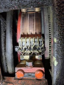 Each of those holders consists of two brushes back to back, for a total of six. That large number of brushes is required to conduct current that can be upward of 2000 amps. Also notice the small, hooked wires on top of the brushes. These are spring wires that put downward force on the brushes which forces them tight against the copper segments. Each spring has adjustment steps that need to be correct for keeping the recommended pressure on the brushes as the brushes wear down. A few of the brushes were found to be slightly too short and new ones will be purchased.
After the generators were cleaned, the locomotive was moved outside the carbarn and the engine was started. Something was wrong. The locomotive would not move under its own power. John and Richard tracked down the problem. It was a loose wire leading to the exciter generator field coil. John repaired the connection and the locomotive moved under its own power, correctly, for the first time in 30 years.
They also had a problem with the air compressor. For some reason, the compressor governor would not open the compressor unloader valves. That meant the compressor would keep working until the pressure was high enough to open the high-pressure safety valve. Ryan Keck had overhauled the governor, but it still didn’t work correctly.
After some troubleshooting, Richard and John found that the pressure pipe going to the governor was plugged with debris. Once they cleaned out the pipe, the governor worked correctly. They were able to adjust it to have the compressor stop working at 140psi and start again at 130psi.
After that was complete, they tested the locomotive by pulling two comet cars on the Carbarn 7 lead. Everything seemed to work correctly.
Near term, a water leak by one of the exhaust snubbers (mufflers) will have to be repaired. That probably means the snubbers will need to be removed. However, once they are removed, there is additional work that will need to be done behind them. That whole area is thick with wet oil and dirt from leaking gaskets. That will need to be taken care of before the snubbers can be put back on.
After that, there are other minor things to attend to such as servicing traction motor blowers, etc. Once those items are taken care of, it will be time to connect the locomotive to the newly refurbished load bank for testing.
That testing essentially disconnects the traction motors from the main generator in the locomotive and routes the electricity from the generator to an external load bank that dissipates the electrical power in large resistors.
We are very short on money and needing funding for this project. If you can, please donate using this Hot Link to the museum’s web site.
https://socalrailway.org/collections/santa-fe-railway/560-details/
USAF 1601
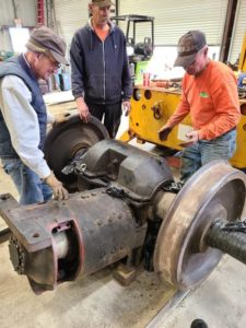 Frank Kunsaitis, Doug Newberry, and Frank Kunsaitis have attached the refurbished traction motor to the gear case. Frank reinstalled the brush assemblies in the motor and the complete combo is ready to go back under the locomotive.
While the traction motor was being repaired, parts that were previously ordered, arrived. They are new wear discs for the bottom of the truck center bowl and new springs and pieces for the brake cylinders. Unless something else crops up, it looks like the repaired trucks can be put back under the locomotive now.
Once that is done, they will be tested to make sure everything looks correct. After that is verified, the traction motor wiring that was disconnected many years ago will be reconnected and tested. If everything checks out correctly, the locomotive will again be using all four axles for traction.
This job turned out to be much more complicated than we anticipated. Fortunately the electric motor repair company in San Diego was able to refurbish a damaged armature commutator that we thought could probably not be saved.
After the trucks are working correctly under 1601, it will be time to address other minor issues with the engines, compressors, missing hardware, etc. Once this locomotive is fully functional, it will probably be the main switching locomotive at the museum.
SP1006 (1939 EMC SW10
The bell ringer was an original 1939 version that was donated to the project, along with the bell and bell mounting yoke. The ringer finally wore to the point that air was escaping, and the bell wouldn’t ring. Brice Brummett and Andrew Temoshek removed the original ringer and installed a newer version that is rebuildable. The original ringer will be looked at to see if it can be saved. If it can be made to work again, it will be reinstalled for authenticity.
OERM 1956
The bell ringer on 1956 was also leaking air so Brice and Andrew change it out also. This locomotive is not part of the museum’s official collection so modifications such as this, don’t pose a historical issue.
LOAD BANK STATUS
 Carl and Doug finished wiring the load bank. It is now ready to test. Once we know that it works correctly, safety shields will be fabricated and installed.
Obviously, testing with up to 1000 volts, and essentially unlimited current, can be very hazardous. The use of the load bank will require extremely strict safety precautions consisting of shields on the unit, safety cones and the appropriate Caution signs.
The load bank is a very large device whose function is to take electricity from a locomotive’s main generator and turn that electrical power into heat. That allows the locomotive engine to operate at high power levels for testing, yet the locomotive isn’t moving down a track.
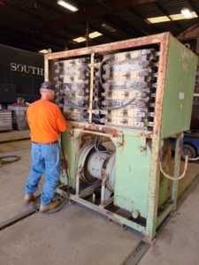
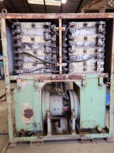 For perspective, in this next picture (right), compare Carl’s size to the load bank. The gray oblong devices by his right shoulder are the resistor grids. They are connected so they all equally share the electrical load coming from the locomotive. The maximum power will be 2000 amps at 1000 volts. That is 2,000,000 watts of heat that must be dissipated. Its also equal to about 2,600 horsepower.
There is a 65 horsepower electric motor driving two very large blower fans. They are the devices by Carl’s knees in the photo. The motor gets its driving electricity from the resistor grid terminals. So, the higher the voltage, and power, from the locomotive, the faster the blower will run.
This next picture (left) shows the large cables that connect the resistor grids. In addition, copper buss bars are used to connect one grid to the next for series connections.
On the front of the load bank are three meters.
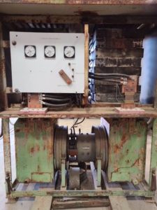
One will show the locomotive main generator voltage, the next will show the current flowing in the system, and the third one will show the voltage going to the blower motor. That voltage will be adjustable using the four taps on the right side of the control panel. It will be very important that maximum air flow be maintained at all times.
Dissipating 2 million watts of power is roughly equivalent to operating 1,500 microwave ovens. That is an unimaginable amount of power being generated by the locomotive.
Dave Althaus