Diesel Service Report, May 21, 2023
ATSF Fairbanks Morse H12-44 SF560 Restoration
The two major tasks remaining before painting the locomotive are to restore the cab and engine compartment. The cab work is well under way. 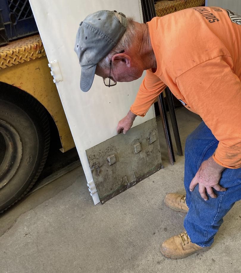 Corey Wylde is heading up that effort and the rest of the crew are pitching in on various aspects of the effort. Some of the latest work has focused on the refurbishing of the front and rear cab doors and one of the the electrical compartment doors. Carl has refurbished the areas that were rusted out and has prepared them for painting. On bottom of the door below, Carl is holding the piece that he cut out and replaced. It had severe damage from amateurish attempts by someone to weld it a long time ago.
Corey Wylde is heading up that effort and the rest of the crew are pitching in on various aspects of the effort. Some of the latest work has focused on the refurbishing of the front and rear cab doors and one of the the electrical compartment doors. Carl has refurbished the areas that were rusted out and has prepared them for painting. On bottom of the door below, Carl is holding the piece that he cut out and replaced. It had severe damage from amateurish attempts by someone to weld it a long time ago.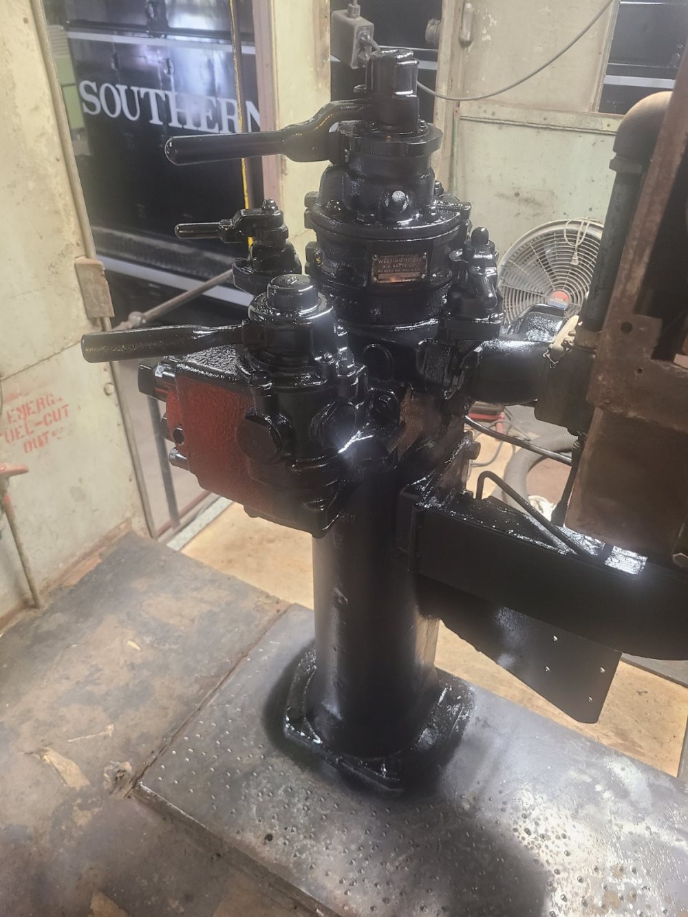 A lot of cleaning and removing of old paint has gone on now for a couple of weeks, focusing on the brake stand and control console. Harry Pederson has been working on that for a number of days. Carl finished the cleaning on the brake stand and painted it black. The brake portions on the brake stand had been refurbished a few months ago so they will probably be the ones used with the locomotive after the refurbishment effort is complete.
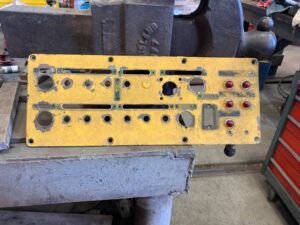
Zachary Halama has sanded the control console so it is now ready to be painted. However the duplex air gauges and the load meter gauge faces still need to be refurbished.
The control console meter and switch panels were removed and are now at a powder coating company being coated with crinkle finished black powder coat. That finish is visible under the layers of additional paint so we will try to replicated it.
The sliding sash windows in the cab have been removed and are being refurbished. The window glass was all broken out so it is being replaced. The original glass was specified as being 3/16′ thick. The more commonly available glass and weatherstrip material is 1/4″ thick so that is what will be used for the replacements. New weatherstrip material is on order. The aluminum frames had numerous coats of various colors of paint. The frames have been delivered to a company for bead blasting and giving them a clear electro plated coating applied.
The other five windows have been measured and new glass and weatherstrip material will be ordered this week. The goal is to have the cab restored and the windows in place before the main painting project begins for the whole locomotive. If things go as planned, the main painting project will start in October or November.
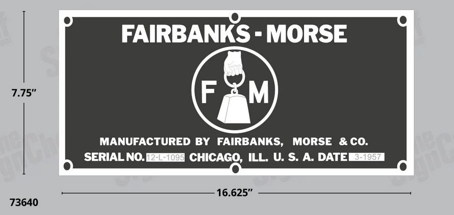
New builders plates are being made. Richard Berk made the stencils that will be used and the artwork has been sent to a company that will make the adhesive applied vinyl decals that will be applied to stainless steel plates.
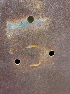 On the front and rear of the locomotive, Santa Fe had attached cast metal identification numbers for the locomotive. Those were removed from the locomotive long ago. Our task was to then try to replicate those those numbers. Evan Werkema found drawings for the numbers. They were originally designed in 1906 and were used on all steam locomotives and even a few Diesels by Santa Fe. But these numbers are not any ordinary font. After a lot of searching, we were able to find a rail-fan that also happens to work in the 3D printing field. He is going to print the correct style numbers “560” out of UV tolerant plastic which we will then paint aluminum to match the original numbers. The picture (right) shows the outline of the number “5” where the original number was attached.
From that shadow and the location of the mounting holes, we can see that it exactly matches the mounting hole pattern shown on the 1906 drawing that Evan supplied. That is proof positive that Evan’s drawing is exactly what was used for the numbers that were originally attached to our locomotive.
SF108 Prelube System
 The decision was made to add a pre-lubrication system to SF108. That allows for pumping oil throughout the Diesel engine prior to actually starting the engine. Its an excellent way to avoid engine wear caused by lack of oil flow and pressure while starting the engine. An electric pump was installed that sucks oil out of the crank case and pumps it through filters and then into the output port of the engine’s main oil pump. That forces oil into the oil passages leading to crankshaft main bearings, rod bearings, camshaft bearings, rocker arm bearings, and many other places.
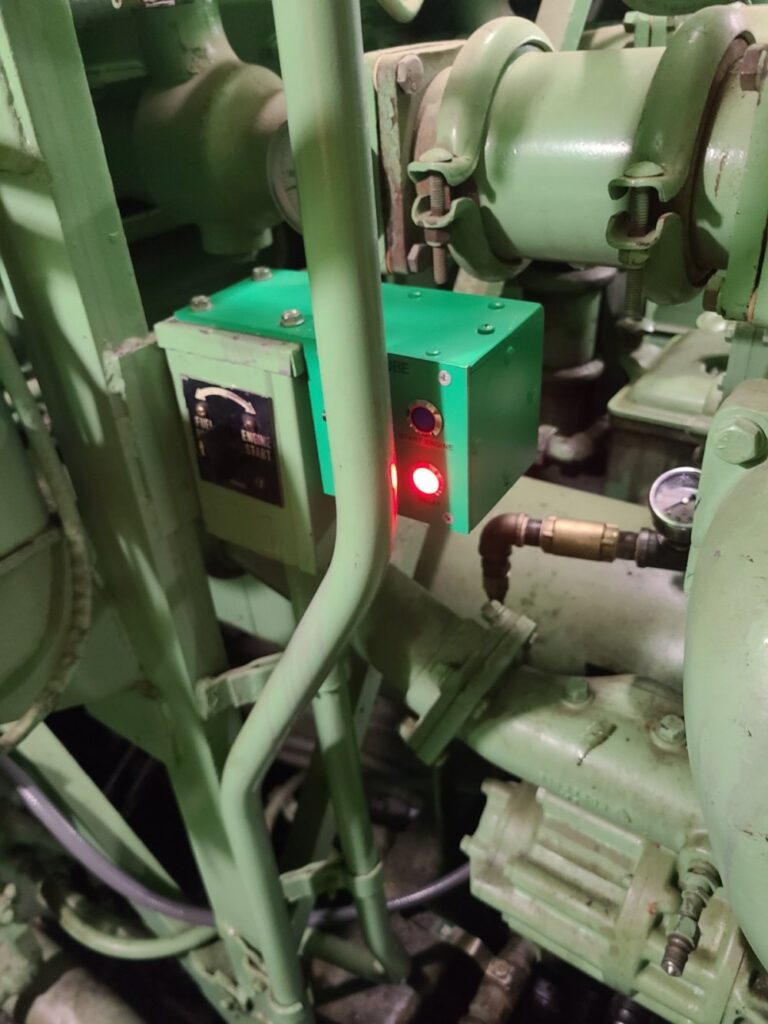
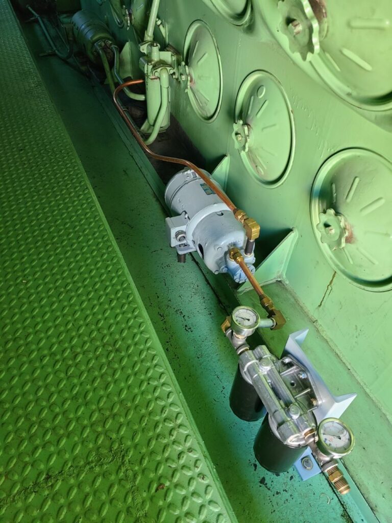
A control system was devised where the Operator turns on the pump and a red light shows the prelube pumping is taking place after 9 minutes that light goes out and a blue one turns on, indicating that the engine can be started. This picture (right) shows the new pump and oil filters.
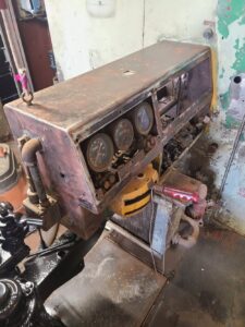
This picture left shows the new prelube control panel mounted next to the Fuel Prime / Engine start panel.
The prelube Turn-On switch is hidden behind the vertical pipe in the picture.
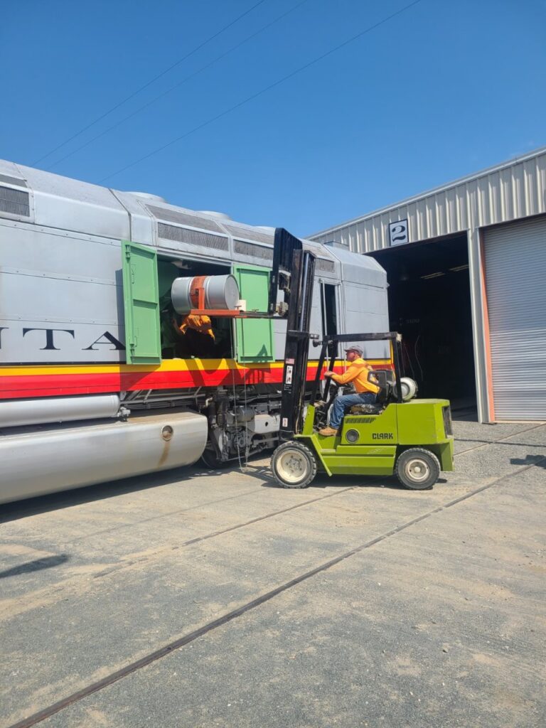
All locomotive engines use lube oil. This one has about 350 gallons in its crankcase.
We have to add oil every year or so, and when we do, its with 55 gallon drums of oil.
Instead of adding a quart or two like you would in your car, we add a barrel or two using a forklift.
SP1006 Issues
During our November Day Out With Thomas event, our SW1 SP1006 all of a sudden lost most of its pulling power. It could pull the train if the engine was running wide open. Then after a few weeks it worked fine again. Then it failed again and would then work again. Two weeks ago it also had fan belts break. These belts were used to drive the generator that keeps the batteries charged. It was difficult to install new belts because none of the adjusting and mounting bolts had been loosened for years. But Richard Berk and John Salvini were able to remove the remaining old belts. Fortunately they were clearly labeled so new ones could be purchased. Then Frank Kunsaitis and Carl Pickus installed the new belts and tightened them. Once the engine was restarted, the new belts work fine.
But the original problem of a lack of pulling power still existed and stayed that way. Fortunately, it was no longer intermittent so the problem could be tracked down and has now been fixed and the locomotive seems to be working correctly again. But we won’t know for sure until the locomotive is used for some switching again.
The rest of this write-up is kind of nerdy if you are interested in wading through it.
In summary, the lack of locomotive pulling power was caused by a lack of field current in the main generator. But there are three field current windings in the main generator. The main one is the Battery field, the next one of interest is the Shunt Field, and the third one is called the differential field and is a hidden one totally inside the main generator. There are no external connections to the differential field.
The battery field current is controlled by the load regulator which is controlled by the Diesel engine governor. The goal is to try to make the horsepower of the Diesel engine roughly match the horsepower being generated by the main generator. Its a very complex issue matching fuel burned in the Diesel engine to the kilowatts being produced by the main generator.
We guessed that the problem was associated with the generator field current so then measured the battery field current. It was in the normal range of tens of amps of current. Thirty amps is a common reading when under load. But, battery field current doesn’t make enough magnetic fields in the generator so another field current is used in addition to the battery field. That second field is called the shunt field. 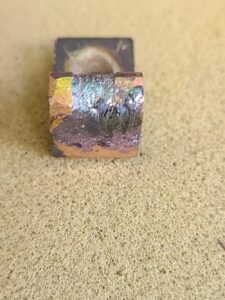 Once the battery field current starts flowing, the generator starts making voltage. That voltage is then fed back into the generator in the shunt field windings. Those windings are polarized in phase with the battery field windings so the two fields add together which produces even more field excitation magnetic fields. So for full power, both fields have to be working.
Once the battery field current starts flowing, the generator starts making voltage. That voltage is then fed back into the generator in the shunt field windings. Those windings are polarized in phase with the battery field windings so the two fields add together which produces even more field excitation magnetic fields. So for full power, both fields have to be working.Close examination of the shunt field contactor showed that it wasn’t closing all the time and one of the contacts was severely burned but the other two that are connected in series with were not burned. This (right) shows the burned contact.
A new contact tip was installed but it was still noticed that the three series contacts were not opening and closing at the same time. Then it was noticed that the common shaft that they were mounted on had severe movement on one end of the shaft. A bearing that was supposed to hold the shaft in level in place, was totally worn out. A fix was designed for that problem but it still didn’t solve the loading problem. 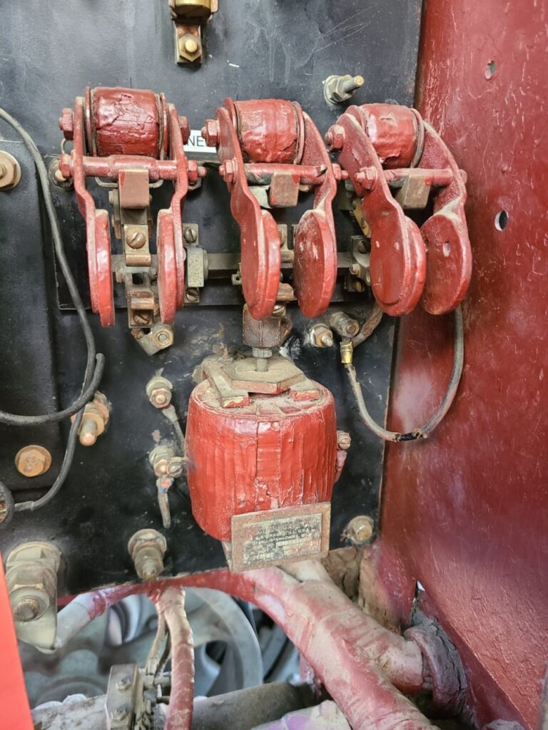 This (left) is the three contact shunt field contactor that had the badly worn bearing on the horizontal shaft.
This (left) is the three contact shunt field contactor that had the badly worn bearing on the horizontal shaft.When the shunt contactor was tested using 64 volts on the activation coil, the contactor aggressively closed and worked perfectly. But when the locomotive was running and 64 volts was routed though numerous other contact interlocks, the contactor was very sluggish and often wouldn’t close. A check of the voltage on the coil showed only 29 volts instead of 64 volts. Using a volt meter and testing the circuits that were all in series with the shunt contactor coil, it was found that one set of interlocks hidden away under the floor on the positive polarity starting contactor was not making good contact. There was carbon built up on the face of one contact and the current flowing thought that carbon was enough to cause a voltage drop from 64 volts to 29 volts.
Once carbon was cleaned out, the system all worked correctly again. So, one dirty interlock on the engine start contactor caused the shunt contactor to not pull in which resulted in low field current in the main generator which resulted in very limited pulling power for the locomotive.