Diesel Service Report, June 7th, 2021
Fairbanks Morse Santa Fe SF560 Restoration
Work has been progressing on SF560 and has been focusing on the exhaust manifold issues for the past couple of months. Both manifolds were damaged years ago when the owners neglected to drain water out of the cooling system when the weather turned cold. The water in the cooling portion of the manifolds, froze and bulged the steel to the point of almost failing.
Replacement manifolds are available but would cost us well over $15,000 for used ones. We only have $20,000 in the project fund so spending that much on manifolds would be a serious blow to our funding.
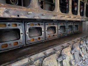
 Instead, we have elected to try and repair the existing manifolds. Jeff Williams started the repair on the first one by removing the bulged wall which exposed the interior of one portion of the water jacket. Jeff took this picture (left) after he removed the faulty bulged outside plate.
A new steel plate will be welded back on top of the numerous standoffs and then the cooling portion of the manifold will be pressure tested.
The second manifold is in the process of having its bulged steel wall removed. Once both of the damaged portions of the manifold have been removed, the interior of that portion of the cooling system will be sandblasted to remove rust and provide a good surface for the adhesion of JBWeld, which will be applied over the inner wall where rust has made the steel very thin. We don’t know if it will work but will try it. The JBWeld company was asked about this application and they thought it would work OK. But they informed us that we should use the original formula of JBWeld because it isn’t water soluble. Apparently the newer versions of JBWeld can be affected if submerged in water.
 We realize there is risk in this approach and have decided to take that risk rather than spend over $15,000 on two used replacement manifolds. If the JBWeld approach fails then we will most probably have to buy replacement manifolds. By then we will be experts in removing Fairbanks Morse OP engine manifolds!
Bob Bray, Tim Johnson, and John Salvini have been working on the engine block where the manifolds mount. The manifold fits snugly into that area and the bulged manifold essentially jammed itself into the that open box area.
Diesel Service Load Bank
Diesel locomotives use electric motors to turn the locomotive drive wheels. Those electric motors get their electricity from a large generator. The generator is bolted directly to the Diesel engine. So, when the Diesel engine is running, the generator is turning. If excitation is provided to the generator, electrical power is generated and is used to turn the electric motors that rotate the locomotive drive wheels. That is why the locomotives are called “Diesel Electric Locomotives”.
But, there is a difficult issue with this approach.
Efficiency in locomotive operation is critical to railroad operations. In other words, they need to use as little fuel as possible and yet be able to achieve the maximum horsepower from the Diesel engines and generators when needed. To do that, the power curves of the Diesel engines must be matched to the power curves of the generators. That is done by engineering the generator excitation power curve to match the horsepower curve of the Diesel engines over the full range of engine RPM. Railroads carefully check those adjustments to ensure their locomotives are properly set up to not only provide the best use of burned fuel but to also ensure that the locomotives are producing the correct horsepower at specified RPM’s of the Diesel engine. This becomes very important when determining how many locomotives it will take to pull very large trains. And, it is important that each locomotive is capable of providing that expected horsepower.
The problem is that there is no easy way to put the locomotive under full load for testing. To do that would require the locomotive to be pulling a large train, up hill, with the throttle wide open, and then measuring the voltage and current coming out of the main generator. That just isn’t possible. Instead, the railroads use a test device called a “Load Bank”. The load bank consists of very high powered resistors that are connected directly to the main generator. The locomotive then delivers its electrical power to those resistors rather than the traction motors to turn the locomotive wheels.
When that load testing is being done, the locomotive will be standing still, its Diesel engine will be at full speed and horsepower, the generator will be producing its maximum power, and that power will be going directly to the load bank resistors. It sounds simple, and in a way it is. But its very awesome to witness. Being next to a locomotive that is running wide open, under load, and a load bank cooling blower running wide open, results in extreme high levels of noise. And it continues for many minutes until the locomotive engine temperatures become stable.
After the temperatures in the engine stabilize, the current and voltage produced by the main generator are read off from meters in the load bank. Fortunately there are a couple of simple formulas that can quickly convert those meter readings into horsepower.
Amps x Volts = Watts
There are 746 Watts per horsepower.
As a rough rule of thumb, 600 volts is a normal level of voltage used in locomotive traction motor systems. So, if a locomotive is rated for 2250 horse power, that is equal to 1.679 million watts. But in the case of our E8 locomotive, that is the rating for two Diesel engines. One engine then should be able to produce about 840,000 watts. If we divide that by 600 volts, the result is that there should be a current of about 1,400 amps. Obviously those are extremely large numbers to think about. And, that is just for a Diesel engine that is rated at 1125 horsepower.
The load bank has to be designed to absorb those 840,000 watts and turn that energy into heat. The resistors are obviously very large and are cooled with a very large fan.
The museum obtained a carcass of a load bank from Taylor Yard in Los Angles when the yard was shut down 15 years ago. The load bank carcass sat unused at the museum until last year when we realized we really needed it for engine testing.
The load bank had been stripped of all of its resistors, copper wiring, and resistance selection switches while it was at Taylor Yard. We had nothing except for a carcass with a blower. Fortunately, we helped scrap out a GE U28 locomotive about 20 years ago and were able to save the dynamic braking resistors from that locomotive. To our amazement, those resistors were exactly the same as had previously installed in the load bank. Our task then was to install the resistors and design a wiring configuration that would provide roughly the correct resistance value for testing the locomotives.
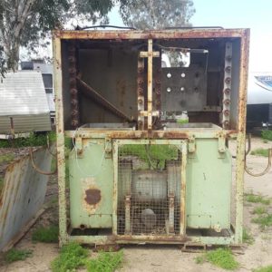 This (left) is the load bank after it came to the museum from Taylor Yard.
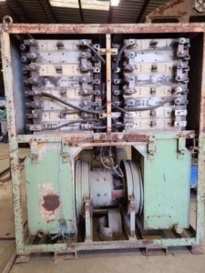 The first task was to install the large resistors. This next picture (right) shows the resistors in place and some of the interconnect wiring. The load bank is designed to handle up to 2,000 amps. There are three parallel sets of resistors, so each of those sets must handle 1/3rd of the current, or 667 amps. The size of the cables was selected to handle that high current.
The final problem was the missing switches and meters that were needed for the load bank to function properly. We didn’t have any of the switches. They are very unique and capable of handling large currents. Instead, we decided to not use switches. We designed the resistor connections to provide .417 ohms. That value is approximately in the correct range for essentially any locomotive that we have. Its not exact so it doesn’t perfectly replicate the load produced by the locomotive traction motors, but is close enough for our museum testing. And that much simpler to design and build.
After the resistors were installed and the wiring was complete, Carl Pickus fabricated outside panels to totally enclose the resistor bank. That forced the cooling air to go up through the resistors for the best cooling possible. Once Carl was finished, he delivered it to George Chapman in a different car barn for painting. George painted the load bank with official Southern Pacific Sea Foam Green colored polyurethane paint. That should last for many years. Thanks George. It looks great.
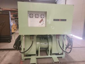
Now we have a professional looking load bank. The General Electric sign was donated by John Stumreiter. We have no positive proof that it was originally a GE load bank but do know the GE resistors fit the openings perfectly and the blower motor has a GE ID tag on it. So, we will say it’s a General Electric load bank, designed specifically for our museum.
UP942, our EMD E8 Locomotive
UP942 arrived at the museum many years ago and has been frequently used for special operations, Run-One’s, and normal weekend running. The locomotive has two Diesel engines in it. One supplies power to the front truck and one supplies power to the rear truck. The load meter in the cab only shows the current being applied to the front truck, and the assumption has to be that the same amount of current is being supplied to the rear truck, if everything is working correctly.
When the load bank was first tried on UP942, it was connected to the rear engine and generator. Immediately something wasn’t right. It was producing only half of the expected 1125hp. John Salvini quickly realized that the main generator shunt resistor must be broken. He and Richard Berk checked and, sure enough, the resistor was bad. After the resistor was repaired and reinstalled, the load bank was again connected to the rear engine. This time the horsepower was above 1000, close to where it should be.
And, this problem would have never been noticed if we didn’t have the load bank to do the testing with.
While testing the rear engine the second time, after a number of minutes of running at full load, the engine overheated and shut down. It was then noticed that a set of cooling louver vents were not opening properly. There was a faulty pressure cylinder. We had a spare one in stock and John and Richard installed it. Then the testing continued with no further issues found.
As Eric Levin, our technical adviser from back east commented, “The Big Box Finds All”, meaning if you want to really prove something is working correctly, use a load bank. We sure learned that lesson quickly.
– Dave Althaus