Diesel Service Report, July 31st, 2021
Fairbanks Morse Restoration Project
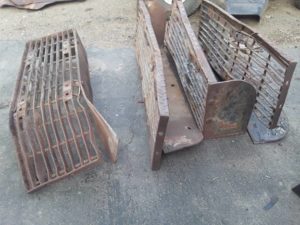 When the locomotive was shipped to the museum from Texas in the mid 1980’s, pictures verify that the front foot-boards were still on the locomotive. After that move, they were removed and stored at the museum. And eventually no one remembered where they were. Phil Palmieri located them a couple of weeks ago. The foot-boards were then retrieved and moved to Carbarn 7 for restoration. They were severely mangled after working in the Texas scrap yard for over 15 years.
 We also realized that Santa Fe had significantly modified the foot-boards to incorporate an extra tall shield to prevent crewmen from accidentally sliding their foot past the smaller vertical guard. The new shield was a large steel sheet that was bent to connect the foot-board’s smaller shield to the sill plate of the locomotive.
The project restoration goal is to restore the locomotive back to its 1957 “as delivered configuration”. We know that that large shield wasn’t on the foot boards in 1957 and will remove them. But that also means that the foot-board steel support brackets needed to be modified slightly, back to their original shape.
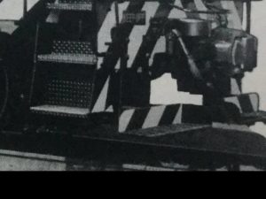
This next picture was copied from the 1957 Operators Manual which was written specifically for Santa Fe for this specific order of locomotives. This proves that the foot-boards were originally installed in a traditional manner. In addition, it clearly shows how the black and white stripe paint pattern was applied to the foot-boards when new.
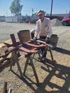
 Carl Pickus took the mangled foot-boards home and disassembled them. He then used his large hydraulic press to rebend the support brackets back to their original shape.
But it is obvious that the tread step assemblies themselves are not salvageable. Possibly the original small safety shields can be retained, but if not, Carl will fabricate new ones.
After looking at the mangled tread steps, it was clear that they were designed and fabricated as a single 11″ x 36″ units. The spacing and location of the bars and and connecting rods is exactly laid out for the length and width of units. And they have special round leading edges consisting of tread plate that has been formed to the front of the steps. Its possible that they could be reproduced by hand, but it would be dozens of exacting hours of work. Our time is too valuable to take on that task, so replacement tread steps have been purchased. They are readily available with the correct dimensions needed.
 The next step was to reattach the foot-board brackets to the end the sills of the locomotive. Doug Newberry and Carl sand blasted and primed the brackets and prepared the correct mounting hardware.
Carl then bolted the brackets onto the locomotive making sure that they were evenly spaced. However, as with much that is done on locomotives, the locations of the original mounting holes were close but not close enough in their spacing. Carl then slightly elongated a couple of the mounting holes to ensure that the brackets were square and plumb with each other. By the end of the day, all four brackets were correctly installed.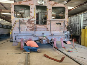
Frank Kunsaitis continued to work on the radiator shutter system. The manual operating levers were cleaned up and reinstalled. However, it quickly became obvious that previous modifications to the shutter opening and closing mechanism was not adjusted correctly. After some fiddling with angle adjustments on shafts and clamps, the shutters do open and close manually. But, there is an issue with correctly adjusting the movements of the air operated pistons. That work will continue next week.
As previously reported, the cooling fan assembly is not the correct one for the locomotive. There is no chance of obtaining the correct mechanically driven fan and all its associated parts, so we will do what is necessary to make the existing electrically driven fan operate adequately for our museum operations.
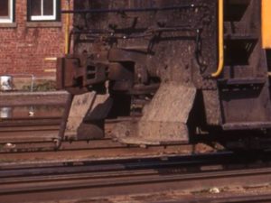
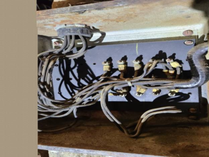 That effort entails installing a new thermostat switch which is now done, and the installation of a high current contactor to operate the fan. The problem is that the wiring in the engine compartment is not adequately labeled so it will be difficult, but possible, to trace down the correct wiring. We have posted requests for wiring diagrams on Facebook and hopefully will find what we need. We have circuit diagrams that were provided by Jack Corrick. But we don’t have the physical layout of the wiring in the locomotive. This is an example of what we are dealing with. And the wire labels are mostly missing.
Richard Berk and John Salvini will continue with the installation of the exhaust manifolds with Richard returns from travel in a few weeks. In the mean time, Tim Johnson, Bob Bray, Carl, Doug, and Frank have been cleaning more engine items to make work easier for Richard and John.
– Dave Althaus