Diesel Service Report, February 27th, 2021
Fairbanks Morse H12-44, SF560 Restoration Project

One of the tasks that we knew was going to have to be done, was removing the mufflers to gain access to the front of the Diesel engine. That area is extremely coated with oil and grime and there is a water leak behind the governor and one of the mufflers.
The use of the word “muffler” usually relates to a device that limits sound coming out of an automobile engine. In this locomotive, it is called a “snubber”. It also reduces sound levels of the exhaust, but its other main function is to control sparks being shot out of the exhaust stack. It is supposed to “snub” out sparks. We will continue to refer to the device as a snubber.
 We have known that the locomotive spewed droplets of oil out the exhaust stack long before we received it in the 1990 time frame. That oil, mixed with exhaust heat, caused a continuous build up of oily carbon in the snubber. That buildup pretty well plugged up the snubber drain port and may have also affected the venturi action that was supposed to keep the engine air inlet filters free of accumulated separated dirt particles. There is no option other than to remove the snubbers for cleaning and repair work in the general area.
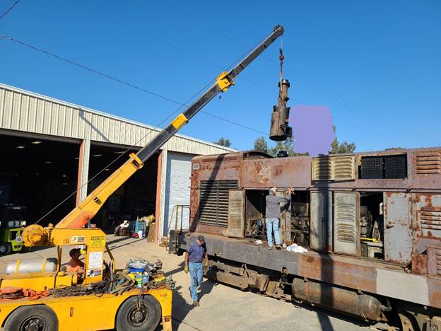
John Salvini spent a number of hours removing the governor, fuel piping, and other fittings before the snubber could be lifted out. It’s a severe understatement to say that he really gets into the task at hand. The snubber is the large round can looking device near the top of the picture.
After John, Richard Berk and Frank Kunsaitis removed the rest of the attachments to the snubber, Carl Pickus used his deck crane to lift the snubber out of the top of the engine compartment. As you can see, this snubber is a serious piece of equipment. It weighs many hundreds of lbs and was extremely difficult to remove.
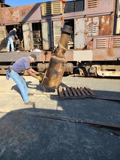 After the snubber was removed, it was placed on a pallet. The plan will be to remove the second snubber this coming Tuesday if the plans all come together. The next task will be to devise a way to remove all of the built up carbon from inside the snubbers.
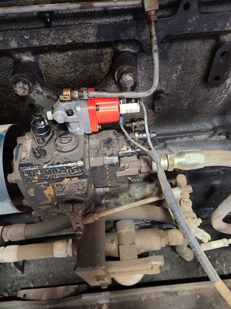
Last month one of the replacement fuel injection pumps froze up, similar to what happened to all 12 of them during its 30 years of storage. The pump was sent back to the vendor for analysis and we are still waiting for the results. Hopefully the cure will be as simple as adding additional chemicals into the fuel system to provide better lubrication for the pumps and injectors.
Thanks to everyone that has donated to the project. We are about halfway towards our goal of $40,000. If you decide to donate, make sure your check is annotated in the comment section showing that it is to be applied to the M56 project, or just write in “Fairbanks Morse Restoration”. Thanks to everyone that has donated so far. You have all been terrific!
USAF 1601
This GE 80 ton center cab switcher is now being used for day to day switching operations at the museum. Out 45 ton GE switcher, USAF 7441, will now be stored inside Carbarn 7 as we continue to refurbish its exterior and attend to details that have long been postponed.
 1601 has had engine shut-down problems since it arrived at the museum. The problem centered around a device called a “shut-down solenoid”. A replacement was obtained and installed. It solved the problem. However, the original solenoid was designed for 32 volt systems. The replacement was made for a 24 volt system. That required a dropping resistor to reduce the voltage to the correct level at the solenoid terminals. After the original solenoid was removed, it was tested for coil conductivity. It measured 51 ohms. The 24 volt version was 30 ohms. So, it is probable that the original magnetic core portion of the solenoid is still functional but the fuel valve inside the valve body was failing. We will reinstall the original magnetic coil to see if it still works. If it does, it will be used and the new dropping resistor will be removed. This (left) shows the new solenoid in place after Frank finished the swap.
 Tom Platten spent a few hours trying to polish the front of the locomotive to see if the paint oxide could be removed. It worked to some degree but appears to need some very aggressive rubbing compound to restore the blue color back to its original luster. This isn’t a critical matter, but it would be nice to have a better-looking paint job now that the locomotive will be in everyday use.
The plan for next week will be to change the engine lube oil and filters. Each engine takes 10.5 gallons of oil, or 21 gallons total. Oil is purchased in 55 gallon drums so it will take almost half a barrel of oil for this oil change. But we also know that the oil hasn’t been changed since the locomotive arrived at the museum many years ago, so it will be best to start with new oil now that the locomotive will be used a lot.
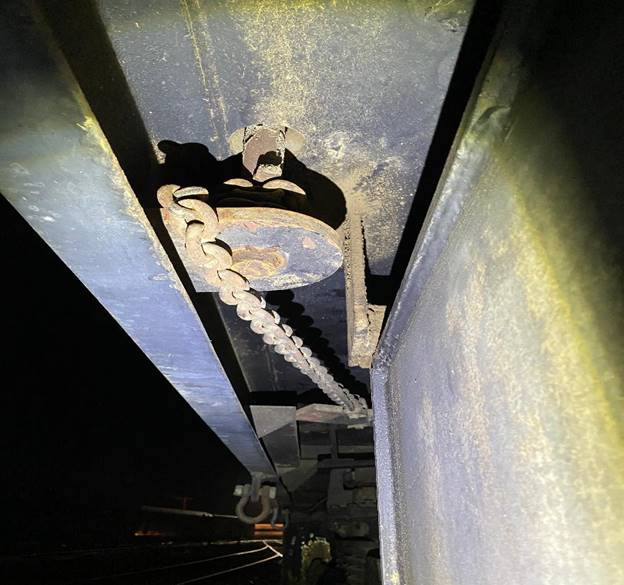
During last week’s switching work, Brice Brummett discovered that the handbrake was not releasing the brakes properly. They found that a hand brake chain guide bracket had failed and fallen off. That allowed the chain to drop off of the chain take-up wheel and get caught. Carl Welded on a new guide bracket so it should work properly again. The picture (right) shows the chain as it is partially wrapped around the handbrake take-up pulley.
Sellers 50 Inch Wheel Lathe Restoration Project
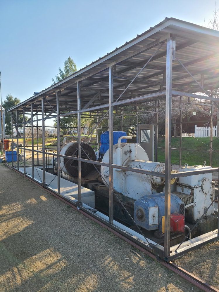
 Carl Pickus, Doug Newberry, and Frank Kunsaitis have finished installing the aluminum roof panels on the newly constructed steel tubular frame that Carl designed and fabricated. Having the new roof in place allowed the protecting tarps over the lathe to finally be removed. Installing the external aluminum wall panels will be the next task. The shed is built as two separate halves. Each half can roll sideways a number of feet which will open the roof wide enough for a crane to lower a complete locomotive wheel set directly down onto the lathe. The picture (left) shows two large gray round devices. Those are the clamping wheel areas where a wheel set is mounted.
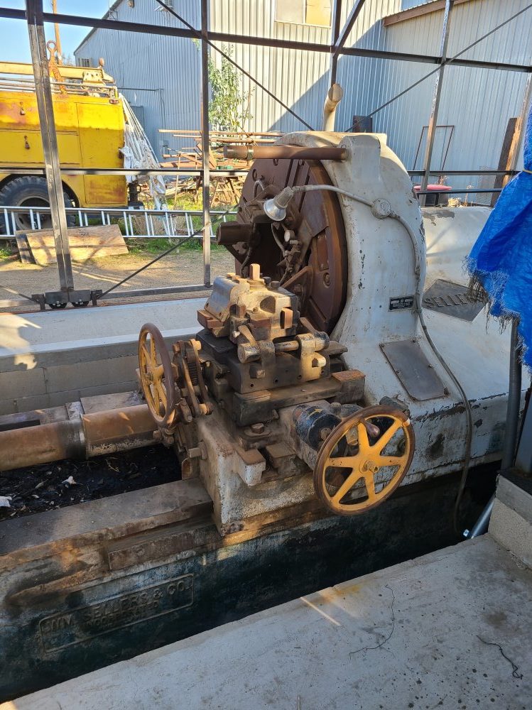
Once a wheel set is mounted in the lathe, each wheel is machined to a specific profile. This picture (right) shows the right hand wheel cutting head and the lathe tool holder cross head. There is nothing dainty about this machine. A special thanks goes to Carl Pickus and Doug Newberry for their continuous work on this project. The new rolling shed is a masterpiece of design and construction. Thanks guys.
Dave Althaus