Diesel Service Report, August 15, 2022
SF560 Restoration
When both trucks were pulled out from under the locomotive, it was obvious that the wheel flanges were way too tall and needed to be cut down. Carl Pickus set up the Iron Horse portable lathe and turned the first three wheel sets until the flanges were an acceptable height. Then when he set up the lathe to turn the fourth wheel set, he found an unacceptable up and down wobble in the wheels. Something was either bent in the axle area or the wheel had worn itself into an out-of-round shape. Regardless, that wheel set could not be used.
We do not have any spare Fairbanks Morse AAR Type A Switcher traction motors or wheel sets, known as “Combos”. But what we had heard was that the Westinghouse traction motors and wheel sets (combos) in our S12 Baldwins could be direct replacement for the faulty Fairbanks Morse. Those Baldwin locomotives came from Trona California where they worked in a Potash production facility. That mineral corroded essentially everything in the locomotives to the point that it is most probably not reasonable to every consider restoring them. As such, they are considered as parts locomotives if needed. Fortunately, the Potash didn’t get inside the Baldwin Westinghouse traction motors.
Six weeks ago we started researching to see if the Westinghouse combos are actually direct replacements for the Fairbanks Morse combos. That then led us back to the late 1940’s and early 1950’s when Fairbanks Morse was trying to get into the locomotive manufacturing business.
There is a lot of history regarding the complete product line of locomotives that Fairbanks Morse built but we are only focused on their switcher line of locomotives. So we needed to understand the Fairbanks relationship with Westinghouse during those years.
John Salvini uncovered a very interesting article in the November 1964 issue of Trains Magazine. The following summarizes some of that information:
FM started building model H10-44 locomotives in 1944. Those were equipped with Westinghouse combos. In 1949, FM designed their own traction motors and generators and from then on the FM combos were standard but Westinghouse combos could be ordered as an option. In 1950, FM dropped the H10-44 model from their line-up and introduced the H12-44 which is what our FM locomotive is. It was essentially identical to the H10-44 but had 1200 HP rather than 1000 HP. The FM combos were also standard with the H12-44 model but Westinghouse combos could be ordered by the customers.
Then in 1953, Westinghouse notified its locomotive customers that they, Westinghouse, would no longer manufacture traction motors and generators for locomotives and would take no new orders. FM then told their customers that they could order Westinghouse electricals as long as there was a supply of them left.
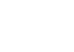
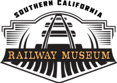
It only makes sense to us that if FM was offering the WH electricals as an option, that they, FM, would make sure that selecting WH electricals would entail very little, if any, additional work building the locomotive. So, with that assumption, we went ahead and removed two combos from under one of our S12 Baldwin locomotives. Then we would choose the best one to install in the FM truck.
After a lot of heavy work, the Baldwin combos were removed and one of them was then installed in the FM truck. The physical interchangeability was proven. The WH combo fits perfectly into the FM truck. There were two minor exceptions. The first was that the traction motor leads on the WH combos were about 8’ long while those in the FM truck were about 4’ long. That’s not a problem. The WH leads will be cut to length and the correct lugs soldered on. The second difference was the traction motor cooling duct. The FM design uses spring loaded steel ducts that were held in place with about a dozen springs. The WH combo uses a rubber bellows duct that is bolted to the truck frame. Those holes were not present in the FM truck frame because they weren’t needed with the original FM combos. Carl Pickus drilled and tapped the needed holes in the FM truck in order to use the WH air duct.
The one topic that we could find no information on is associated with the electrical characteristics of the WH traction motor compared to the FM traction motor. From experience we know that all traction motors are wired essentially the same internally and only vary slightly in copper resistance. Its our guess that FM closely copied the WH motor design to ensure that the FM motors could be used interchangeably with the WH motors. Regardless, in our museum operation, any small electrical changes will make no difference.
The other issue that we didn’t have an answer for has to do with gear ratios of the wheel set bull gear and the traction motor spur gear, some times called the pinion gear. Both FM and WH are listed have having standard ratios of 68/14. But both Baldwin and FM offered different gear ratios if the customer wanted higher or lower gearing when the locomotive was purchased.
We know we could go through the effort of counting the teeth on the two spur gears. Its difficult to do and is very messy due to the crater grease in the gear case. But the reality is that we don’t have an affordable alternative if we were to find the gear ratios slightly different. Most probably the gear ratios are the same and it’s not a problem. But if they are different, we will never know it. The traction motors in each truck are wired in series all the time. As such, the exact same amount of current goes through each traction motor. That causes torque in the motor armature which attempts to turn the truck wheels. But the wheels all have to turn at the same rotational speed so the end result is that different gear ratios result in one traction motor doing slightly more work than the other. Of course its best to have identical gear ratios in all four combos. But if they are slightly different, its not noticeable unless the locomotive is producing full power. In that case, one traction motor might heat up a little bit more than its mate in the same truck.
Now that the FM combo problem has been resolved, work will begin rebuilding the brake rigging on both FM trucks. We will have many of the parts on-hand but will need to buy a number of items that are too worn, and we don’t have spares.
As mentioned, we had removed the two combos from one Baldwin truck. But we needed to put that truck back under the locomotive again so the locomotive could be moved outside into storage. All AAR Type A switcher trucks appear to have identical dimensions for the journal boxes and brake rigging. We decided to try and install two EMD scrap wheel sets that we had in stock. Those wheel sets fit perfectly in the Baldwin truck frame. The locomotive was then towed back outside for storage.
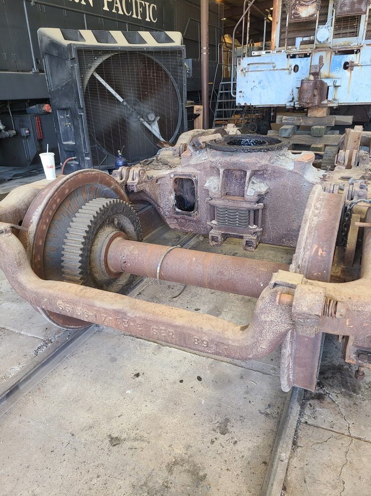
This (below) shows the EMD scrap wheel set being readied to roll under the Baldwin truck.
The wheel set was rolled under the truck and the journal boxes from the Baldwin truck fit the EMD wheel set perfectly.
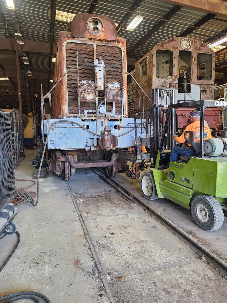
Then the forklift was used to push the truck back under the Baldwin locomotive.
Of course all of this work couldn’t have been done without the dedicated volunteers. Removing trucks and combos and then reinstalling them, is hard dirty work. Thanks goes to John Salvini, Carl Pickus, Tom Platten, Frank Kunsaitis, Corey Wylde, Tim Johnson, Doug Newberry, Bob Bray and Richard Berk for their help with all this work.
– Dave Althaus