
Diesel Service Report, April 3rd, 2021
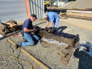
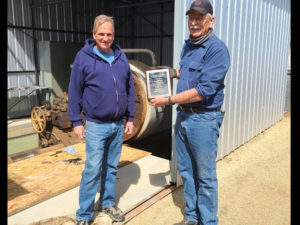 A few weeks ago, John Salvini was selected to receive the yearly President’s award. For those of us that know and work with John, it was richly deserved. As you will note in this, and later reports, John is a key person in our organization. On the left is Hank Winn, our General Manager, presenting the award to John.
Fairbanks Morse H12-44, SF560 Restoration Project
Shortly after the restoration project began, a pretty severe water leak was noted around the governor. At first it was guessed that the leak was due to a faulty gasket or flange surface. John removed the governor and much of the front plumbing and then he and Richard Berk, with Carl Pickus using his deck crane, removed the muffler snubbers to gain access to the area.
There were some leaks associated with gaskets and flanges but those weren’t the only areas that were leaking. Further research in the technical books, and investigation of where the water was coming from, indicated that there were probably bad gaskets between the exhaust manifold and the block. It was exceedingly difficult to do, but the exhaust manifold was removed. Once the manifold was removed and some of the rust and grease removed, the real problem became evident. There were numerous holes in the bottom of the exhaust manifold. Untreated water apparently sat in that area for many years an finally ate its way through the metal.
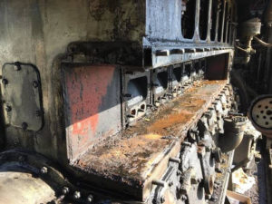 This picture (left) shows the cavity where the exhaust manifold bolts up against the output of the six cylinders. This is just one side of the engine. The other side has a duplicate arrangement. The six oblong holes on the vertical wall inside the cavity, are the openings from the cylinders. That is where the exhaust comes out and goes into the exhaust manifold and then to the snubbers and out the stack. But also notice the smaller oblong holes just below the larger ones. Those are water passages that feed water to the power cylinders for cooling them. The exhaust manifold is performing two functions. The first is to get exhaust out of the engine but the second is to route water into the cylinder jackets for cooling. That cooling part is the area that is now giving us problems.
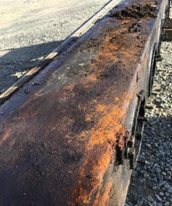 This next picture (right) shows the manifold after it was removed. In the picture the manifold is upside down to reveal the bottom of it. Once it was tipped over so the bottom could be seen, the problem became obvious. The manifold has numerous leaks from its water jacket. Since it is upside down in the picture, it shows where rust and corrosion have collected for years. And of course, the water was not treated with anti-corrosion chemicals so the rusting process just ate away the steel plate.
Once the surface was cleaned off, at least six holes appeared. And of course, once rust holes appear, it guarantees that the area around the holes is also thin from corrosion. So, it isn’t as simple as just plugging the holes. They have to be made much larger before new material can be brazed, or welded, onto the area. And in this case, there is very little room to add thicker material because the manifold sits in a very confined channel in the engine block. Also note the numerous spots that look like dimples in the top plate in the picture.
 Those are welding plugs that attach the outer plate of the water jacket to the inner wall of the manifold. The distance between the two plates is much less than one inch. The plug welds help keep the two plates properly spaced. But also notice the rounded bulges in the top plate. The is normally evidence of having freeze damage if the water passages were not properly drained and freezing weather took place. Normally, freeze damage results in elongated cracks. So far, we have not found that.
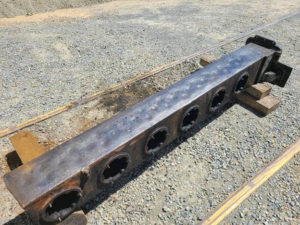
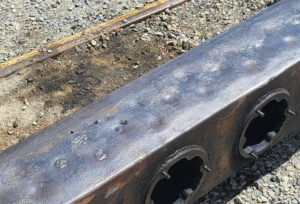 This next picture (right) shows a close up of the expanded metal. Its also possible that there was no freezing and that the metal rusted internally to the point that the rust caused it to expand. We have no proof which effect caused the expansion. But we aren’t seeing damage other than the rusted out holes, yet.
Since the exhaust manifold has water jackets internally on all of its surfaces, its mandatory that a means must be provided to drain that water to avoid damage from freezing or long-term storage. Those water jackets are very narrow. This next picture shows two drain plugs. The manifold is upside down in the picture, so the upper drain plug is for draining the water jackets. The lower plug is for draining any accumulated oil or water that may be inside the manifold. Obviously neither of these plugs have been removed in many years.
 We don’t know yet if we can salvage the manifold(s?) or if we need to hunt for a replacement(s). Further, this is just one of two exhaust manifolds. If this one is this bad, what are the odds that the other one is in essentially the same shape? We should know more in the next couple of weeks. In the meantime, Richard and John have been cleaning this one in hopes that it can be reused.
A few months ago, we found that one of the replacement fuel injection pump plungers was frozen solid and a couple others were starting to feel tight. The frozen one was removed and sent to the vendor for analysis and repair. The pump has been overhauled and returned. It was their belief that the pump plunger had become stuck to its cylinder walls due to dirt or grit of some kind. What this means is that when the engine is back together and ready to run again, a very complete flushing process must be done to ensure there are no contaminants in the fuel lines.
SP1006
Ever since the refurbishment project was finished, oil has been accumulating in the U channel on top of the engine, between the two exhaust manifolds. We still don’t know where that leak is. Frank Kunsaitis has Red Tagged the locomotive for a week and put some rags in that area to soak up the loose oil. Once the rags are removed, he will start the engine to see if he can finally locate where the leak is. Other than that oil leak, the engine has been performing perfectly.
UP942
During load testing a few weeks ago, a failed main generator shunt resistor was discovered. That resulted in the rear engine producing only half of its rated 1200 horsepower. A replacement shunt resistor panel has been located and will be installed when it arrives. Thanks Eric.
Load Bank
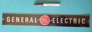
The recently completed load bank was tested on UP942. The load bank appeared to work satisfactorily. Doug Newberry and Carl Pickus have sanded down much of the unit and it will now be painted. When we obtained the empty hulk of the load bank, there were no identifying marks on it. We knew it had a GE blower assembly and GE dynamic braking grids fit perfectly into it. As a result, we are assuming that it is actually a GE load bank. Once it is painted, a General Electric sign will be attached to it. John Strumreiter donated the sign.
Dave Althaus