Diesel Service Report, July 3rd, 2021
UP942
John Salvini and Richard Berk continued to use the newly built load bank to test the Diesel engines up UP942. The rear engine was found to have a faulty temperature switch which was repaired. After the repair, the engine ran fine and produced its full rated horsepower.
They then connected the load bank to the front engine but quickly found that the Ground Fault Relay was tripping while starting the Diesel engine. The ground fault system is part of the high voltage system in the locomotive so it doesn’t get connected to the low voltage 64 volt system other than when the engine is being started. If the Ground Fault triggers during starting, that’s a good indication that there is a short between the locomotive chassis and either the positive or negative side of the 64 volt system. John traced the problem to a low resistance short in the 64 volt auxiliary generator armature. Normally those types of shorts cannot be repaired without replacing the armature or the complete generator. We will be looking for a replacement generator.
When testing the front engine, it produced full horsepower and began to burn off years of accumulated oil that had dripped down the exhaust stack. These locomotives were designed to be operated under heavy loads which resulted in the exhaust systems being very hot. That heat kept the exhaust systems clean of liquid oil. The only way we can burn off the liquid oil is to use the load bank to create enough heat in the exhaust system to keep it clean.
SF560 Restoration Project (Fairbanks Morse H12-44)
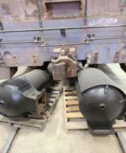 When the museum acquired the locomotive 30 years ago, the exhaust snubbers (mufflers and spark arrestors combined) were severely loaded with hard carbon chunks. The snubbers have been removed and sent to a commercial radiator shop for cleaning. They have been cleaned and repainted with high temperature paint and are ready to be reinstalled. Thanks to Doug Newberry for funding that effort. The snubbers are stored by the rear coupler, waiting to be reinstalled.
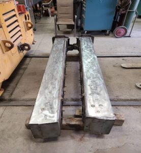
The next major effort was to repair the exhaust headers. These are liquid cooled and subject to damage if not drained properly during freezing weather. Of course, this locomotive was in El Paso TX for many years and received very little attention. As such, the exhaust headers did freeze and damaged both of them. Our options were to either buy used replacements or attempt to repair the ones that came off the engine. The decision was made to at least attempt to repair them. If that failed, then we would have to buy replacements.
Jeff Williams purchased the replacement sheet metal and removed the severely damaged areas on both headers. Carl Pickus then fabricated replacement pieces using Jeff’s material. Jeff then welded one on the first header and Carl welded the second one the second header. Carl then fabricated sealing plates to block off cooling water openings in the manifolds and pressurized the cooling sections to 30 psi. He then repaired a few pin-hole leaks that were found. The exhaust headers are ready to be reinstalled now.
 Tim Johnson and Bob Bray finished cleaning the areas where the exhaust headers are mounted in the engine.
While the headers were being repaired, John and Richard continued to inspect the engine to see if there were any other issues that might give us troubles later. They found the timing chain tightness was not in tolerance but when they checked the engine timing, they found it to be exactly correct. For now, the timing chain adjustment won’t be addressed. The chain and gears looked to be in exceptionally good condition, just not adjusted as tight as the book calls for.
They inspected the cylinder liners looking for undue wear or damage. No damage was found but the liners do show signs of some wear. Not worn out, just not new anymore.
One surprise was that a compression ring was missing on one piston. It was the third compression ring in from the head of the piston. Obviously, it has been that way for a long time. It appears that the ring was not installed sometime in the past. The piston lands look to be in perfect shape and there are no gouges in the liner. The ring is just missing. We won’t address that problem until later.
The one thing that was noticeable was that oil from the top crankshaft area leaked around all of the upper piston rings. Some more than others This was very evident when barring the engine over during the liner and piston inspection process.
This brings up a somewhat controversial topic regarding what causes FM engines to habitually spit oil out the exhaust stack. There are a couple of generally accepted ideas as to how liquid oil gets into the exhaust system. The first concept is that the FM opposed piston engines leak oil into the combustion chamber when operating at low speeds and under idle RPM’s.
That leaking oil would not combust and would be expelled into the exhaust header where it would form oil puddles. Then the exhaust fumes would exist the combustion chamber with significant velocity and energy to stir up those puddles so that the liquid oil would levitate and spray into the exhaust stream and get blown out the stack.
The next theory is that liquid oil leaks into the scavenging air blowers through faulty seals. That oil then would be blown into the cylinders. In EMD locomotives, that is a common problem. It appears that is not an issue in FM blowers. This conclusion was reached after having discussions with Billy Rogers, the founder of BRECO International Inc.
Billy has over 50 years of experience working with FM engines and started his company about 20 years ago. Fairbanks Morse acquired BRECO 6 months ago and has retained Billy for his expertise.
Billy assured us that FM blower seals essentially don’t fail. In his 50 years of work, he has seen only one or two failed blower seals. The way he describes the seals, they are labyrinth seals that essentially don’t fail. He then went on to explain why the FM engines are notorious for blowing oil.
This is what he knows from his years of experience. First, everyone knows that there is a high volume of loose oil in the upper crank case. That oil lubricates the upper rod and main bearings plus provides lubrication for the piston cylinder walls. There is a high volume of oil being pumped around and through the upper crankcase. When the engine is running, the pressures inside the cylinders are from combustion and exhaust scavenging. In other words, there is always pressure in the cylinders between the two opposing pistons. That pressure keeps oil from dripping past the piston rings.
But, when the engine is shut down, the loose oil in the upper crankcase runs down the cylinder walls and seeps, or leaks, past the piston rings. The amount of oil leaking is variable depending on the wear status of the rings and liners. But he says that even with new rings and liners, the oil will leak past the upper piston rings and settle on top of the lower pistons.
When Richard and John were inspecting the piston rings and liners, they could clearly see oil leaking past the upper piston rings while barring over the engine. That would coincide with the discussions that were held with Billy.
Since we can’t stop oil from leaking down onto the lower pistons, It is believed that our best solution is to ensure that loose oil in the exhaust manifolds and snubbers gets burned away during engine running under high load conditions. We know the exhaust manifolds and snubbers are now clean so there is no oil buildup waiting to be blown out the stack. We think we can control that in the future by load testing the engine to keep it cleaned out. We won’t be able to stop the oil from getting into the exhaust header but we have a way to get it cleaned out.
We know that every time the engine is shut down, the oil in the upper crankcase will leak down into the cylinders. To avoid that as much as possible, it will be advisable to not shut down the engine other than when its time to stop running for the day. We won’t know how often we will need to use the load bank on the locomotive but know it will be totally necessary in order to keep the exhaust system from souping (spitting oil out the stack).
We have had discussions regarding the advisability of cleaning and painting the engine now, while we have it somewhat disassembled, or wait until it is back together and operating correctly. The decision has been made that we will reassemble it, as is, and ensure that it is running correctly and that we don’t have to take it apart again. Once that is done, then we will clean and paint it. What that means is that the exhaust headers and snubbers can be reinstalled as soon as we have the correct gaskets on-hand.
But it also means that the engine cooling system must be functional near term. That requirement led to a review of the status of the existing system.
First, we know that the cooling system fan was originally a mechanically driven fan with an eddy current clutch that was turned on and off by a thermostatically controlled low pressure servo system. That mechanical fan and its drive shaft are gone. The existing fan is driven by an electric motor but there is no generator on the locomotive to power it.
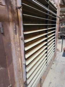 The radiator shutters were all frozen in the open position which meant that the engine would not warm up quickly or adequately. One set of shutters has now been freed up and the other shutter assembly is still being worked on.
There was an originally installed upper set of shutters over the top of the cooling fan. Those shutters aren’t there anymore. However, they were an option and could better control the heat in the engine during extreme cold weather. They won’t be necessary in Southern California.
The cooling system was originally designed to be controlled using a thermostat that varied a low pressure signal line from 0 – 17 PSI. That pressure was used to open the side shutters in a servo manner, open the upper shutters, and turn on the cooling fan. All that control system was removed some time in the past and replaced with a different type of step control thermostat that didn’t use the servo control scheme. Most likely this newer system was installed by Santa Fe.
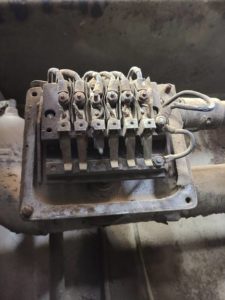 Next (Right) is a picture of the replacement step controller. As the engine temperature increased, different sets of contacts would close which would then turn on the fan and open the shutters at different temperatures. The complete servo control system was replaced with this newer style step controller. Unfortunately, this device was also ruined due to the years of use of untreated cooling water. Note that one of the six contacts is burned off. Someone, most likely in the El Paso scrap yard, tried to turn the electric fan on and off using this device. The fan current was so high that it burned off the contacts. After that, the electric fan was never used.
We are now left with the problem of not having a correct step control thermostat to open the shutters and turn on the electric fan. Work is underway to install a new thermostat that closes at 172 degrees. It will control a heavy current contactor that will operate the cooling fan using 75 volts DC and will open a solenoid that will allow high pressure air to operate piston cylinders to open and close the shutters. This will all happen at 172 degrees. When the temperature drops below that, the shutters will close, and the fan will turn off.
According to the FM Enginemen’s Manual, the engine temperature should be around 150 to 155 degrees F at idle. In cold weather it could drop to around 140 degrees. Obviously, these temperatures are not high enough to keep a Diesel engine running free of internal moisture. We will have to experiment with the cooling system to see what needs to be done to keep it in the right operating range. Rumor and comments by others indicate that the FM locomotive engines tended to overheat when run under heavy loads. Obviously, that should never be the case at the museum. But we could very well have an issue with the engine not getting up to correct operational temperatures.
Another cooling system concern that we have is associated with partially plugged radiator cores and the possibility of a plugged oil cooler. As many of you may remember, we had an extremely plugged oil cooler in SP3100. That was a major effort to solve and was necessary. We know the Fairbanks Morse locomotive has a lot of rust scale in the system so we may need to clean the radiators and/or oil cooler. Fortunately, the cooling water entering the oil cooler comes in from the bottom of the cooler which means any scale in the bottom of the cooler would tend to drop down and form sludge in the bottom of the cooler and could be flushed out. But some rust scale could get caught in the water tubes and plug them. We will know more later.
Unfortunately, cooling water enters the top of the radiator sections so any large chunks of rust scale will have been accumulated on top of the radiator cores. This is an extremely high probability.
The locomotive was originally built and delivered with a single chime horn mounted on the side of the engine hood compartment directly in front of the Engineer’s front window. Santa Fe moved the horn location to on top of the locomotive. But our goal is to refurbish the locomotive back to its 1957 configuration, so the horn is being relocated back to its original position on the side of the engine compartment. Fortunately, we have a correct horn in-stock. We know from a human factors point of view, that the horn is better mounted on top of the locomotive. But, that’s not the way it was originally built.
– Dave Althaus